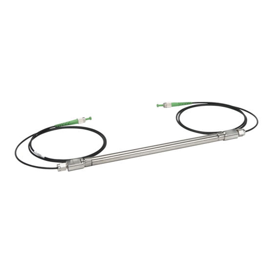
Summary of Contents for Micron Optics os3610
- Page 1 I n s t a l l a t i o n G u i d e | R e v . A Surface Mount Strain Sensor os3610 Micron Optics Inc. phone 404 325 0005 1852 Century Place NE 404 325 4082 Atlanta, GA 30345 USA www.micronoptics.com...
- Page 2 Setting Bar (100 cm) Mounting To Steel (Weldable Brackets): The first step in installing the os3610 strain sensor is welding the two mounting brackets to the surface to be measured. The end brackets are made of 316 stainless steel. Each mounting bracket has two ¼-20 set screws installed as shown in Figure 1.
- Page 3 Long Gage Strain Sensor | os3610 spaced during welding. The Setting Bar has flats cut into each end that properly position the end brackets. Figure 2 – os3610 Setting Bar The Setting Bar is inserted in both mounting bracket and held in place with the set screws shown in Figure 3.
- Page 4 Long Gage Strain Sensor | os3610 Figure 4 – Weld Location / Sequence Allow the weld to cool and remove the Setting Bar. Clean off welding slag and inspect weld. Mounting To Steel (Bold-On Brackets): An alternative mounting bracket shown in Figure 5 is available as an option that can be fastened to the test specimen using two ¼-20 screws.
- Page 5 Long Gage Strain Sensor | os3610 Figure 6 – Concrete Mounting Bracket Prepare the test surface by drilling two ½ inch [13mm] diameter holes properly spaced. To maintain hole spacing and alignment it is necessary to use the Grout-in Drill Guide listed in the “Installation Tools”...
- Page 6 Long Gage Strain Sensor | os3610 Figure 7 – Mounted Sensor Using a torque wrench fitted with a 1/8 hex key, torque the two set screws on the Fixed-end of the sensor. Tighten the two screws to a torque of 75 inch-pounds [8.5 Nm]. The two set screws on the Active-end of the sensor should remain loose.
- Page 7 Figure 10. These parts are available from Micron Optics as an accessory. Sensor Accessories: os3610 Protective Cover and Insulation Kit (25.4 cm) Universal Connector Protection Fitting “PF” Kit This method may not be applicable to all installations due to size or other considerations;...
- Page 8 Long Gage Strain Sensor | os3610 interior of the foam insulator. The insulation is designed so that the fiber can be spliced and excess fiber coiled and stored above the sensor. Figure 11 – EPS Frame Plan ahead and determine where the fiber will enter and exit the stainless steel cover shown in Figure 13.
- Page 9 Long Gage Strain Sensor | os3610 The kit also contains the stainless steel cover shown in Figure 13. This cover provides additional protection to the sensor from weather and physical damage. Notice the cover is supplied with 4 knockout holes to provide a variety of fiber routing configurations. The knockout holes are .88 inch [22.4 mm] in diameter and will accept conduit fittings such as Hubbell Part Numbers...
- Page 10 Long Gage Strain Sensor | os3610 The drawings for the stainless steel cover and EPS insulation are provided for those preferring to modify or provide their own covers. Figure 14 – Cover Lid Drawing Figure 15 – Cover Base Drawings C o p y r i g h t ©...
- Page 11 Long Gage Strain Sensor | os3610 Figure 16 – Insulation Frame C o p y r i g h t © 2 0 1 2 M i c r o n O p t i c s , I n c .
- Page 12 Long Gage Strain Sensor | os3610 Figure 17 – Insulation Lid C o p y r i g h t © 2 0 1 2 M i c r o n O p t i c s , I n c .
- Page 13 One method of protecting sensors supplied with FC/APC connectors is to use the Universal Connector Protection Fitting “PF” Kit from Micron Optics. The Kit shown in Figure 18 contains everything needed to protect an FC/APC connection.


Need help?
Do you have a question about the os3610 and is the answer not in the manual?
Questions and answers