
Summary of Contents for ComSonics OMM Series
- Page 1 User Manual Optical Multimeter...
- Page 2 ComSonics assumes no responsibility or liability arising from the use of the products described herein, except as expressly agreed to in writing by ComSonics. The use and purchase of this product do not convey a license under any patent rights, copyrights, trademark rights, or any intellectual property rights of ComSonics.
- Page 3 CAUTION: The Caution symbol calls your attention to information that, if ignored, can adversely affect the performance of your ComSonics product, or that can make a procedure needlessly difficult. LASER DANGER: The Laser symbol and the Danger alert call your attention to information about the lasers in this product that, if ignored, can cause physical harm to you.
-
Page 4: Table Of Contents
.............................. 7 NSTALLATION ................................7 CHAPTER 4 MAINTENANCE ..........................8 ............................ 8 ATTERY HARGING ..........................8 ATTERY EPLACEMENT ..............................8 TORAGE CHAPTER 5 SPECIFICATIONS ..........................9 Document No.: UM-OMM-2 Rev. A Confidential File Name: OMM Series Optical Multimeter User Guide Draft... -
Page 5: Chapter 1 Description And Function Of Components
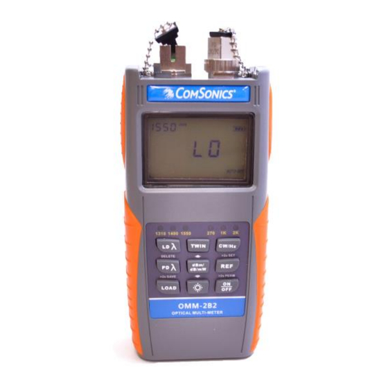
OMM Series User Manual Chapter 1 Description and Function of Components Inventory 1.1.1 OMM Kit includes the following items: A. Optical Multimeter B. User Manual C. USB Cable D. Carrying Case E. Charging Adapter F. 2 1.5VDC AA Batteries Features A. - Page 6 OMM Series User Manual 1.3.2 LCD (Refer to Figure 1-2) Figure 1-2 1. Wavelength currently being measured 2. Reference Indicator: Displays current reference setting 3. Modulation Indicator: Displays modulated CW signal. If none of the tones are shown on the display, then they are all off.
- Page 7 OMM Series User Manual 1.3.3 Key Pad (Refer to Figure 1-3) Figure 1-3 1. Laser source output wavelength LEDs a. Indicates current output wavelength. b. No LEDs lit indicate laser source output is off. 2. Laser source output wavelength selector key. LD = Laser Diode a.
- Page 8 OMM Series User Manual 8. Reference Key a. Short press momentarily displays the current reference value b. Long press (> 2 seconds) sets current Power Meter measurement as the reference level. Two beeps will sound when the reference level has been set and will display dB units.
-
Page 9: Chapter 2 Operation
Dirty connections may cause incorrect measurements and affect network performance. Perform Optical Power Test The OMM Series meters may be used to perform optical power measurements at any point within the fiber network. To perform the test: 1. Clean the OMM fiber connector. -
Page 10: Performing A Fiber Loss Test
To perform a Fiber Loss Test with an OMM Series meter do the following steps: 1. -
Page 11: Chapter 3 Pc Configuration Utility
2. Connect the OMM to the PC using a mini-USB cable and power on. If non-rechargeable batteries have been removed, OPM will operate on USB power. NOTE: The first time an OMM series meter is connected a USB driver will be installed. -
Page 12: Chapter 4 Maintenance
5. Reinstall cover and turn locking mechanism ¼ turn clockwise to lock. Storage OMM Series meters should not be stored in extreme high or low temperatures. Store in a clean, dry location. If device is to be stored for an extended period remove the batteries and store separately. -
Page 13: Chapter 5 Specifications
OMM Series User Manual Specifications Model FHM2A01 FHM2B01 FHM2A02 FHM2B02 Power Meter Parameters: Calibration Wavelength 850/1300/1310/1490/1550/1625nm Connector Interchangeable FC/SC (ST optional) Data Storage 999 measurements Ref.Value Display Units dB/dBm/mW Display Precision 0.01dB Accuracy ±5%±1nW Wavelength Recognition 1310/1490/1550 (input power≥ -40dBm) Tone Detection 270Hz/1KHz/2KHz (input power≥...
Need help?
Do you have a question about the OMM Series and is the answer not in the manual?
Questions and answers