Advertisement
Quick Links
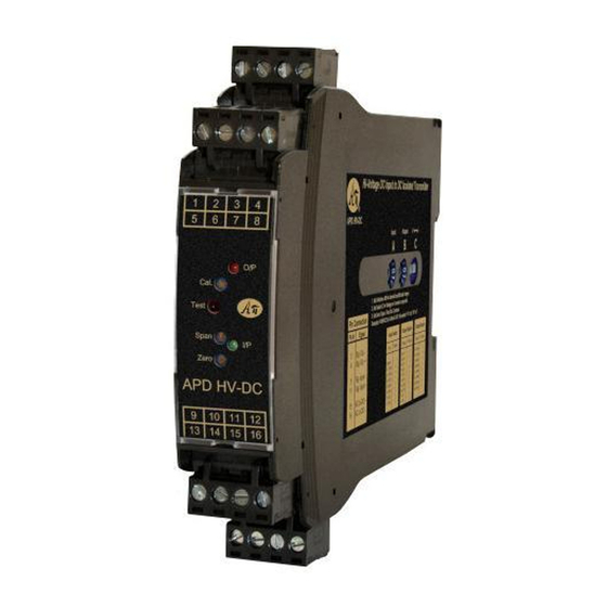
Thermocouple Input Alarm Trips, Isolated, Factory Configured
Input:
Input:
2 or 3 Wire Thermocouple
Most Thermocouple Types
Output:
Output:
Two 8 Amp DPST Relays
Two 8 Amp SPDT Relays
O Factory Set T/C Type and Temperature Range
O Adjustable Trip and Reset Potentiometers
O Input LoopTracker
®
and Alarm Status LEDs
O Full 1200 V Isolation
O Alarm Test, Optional Latching Reset Button
O Automatic Cold Junction Compensation
Applications
Q Process Limit Alarm
Q Monitor, Heaters, Refrigerators, Ovens
Q Process Signal Over or Under Alarms
Thermocouple Input, Factory Configured
Specify T/C type: J, K, T, E, R, S, N, B, C, D, G, M, P
Specify temperature range in °F or °C
Full ANSI temperature ranges
Linearization: 41-55 segment or up to 14th order polynomial
100°F (55°C) is the recommended minimum span
Consult factory if a smaller span is required
Cold Junction Compensation
Automatic for specified thermocouple
T/C Burnout Protection
Upscale burnout protection standard
B option:
Downscale burnout protection
NB option: None
T/C Current
Less than 1.0 µA, including burnout sense
Isolation
Power to input isolation:
1200 V
Common mode protection:
600 VAC
p
LoopTracker
Variable brightness LED indicates input level and status
APD 1200 Relay Output
Single setpoint dual DPST contact sets, field configurable
2 Form A (NO) and 2 Form B (NC) contact sets (8 terminals)
May be field wired for Form C operation
One set point, 12 turn potentiometer, 0-100% of span
One reset point, 12 turn potentiometer, 0-100% of span
Factory configured alarm
Standard:
HI alarm, non-latching, normal acting
APD 1220 Relay Output
2 independent setpoint DPST contact sets, field configurable
SP 1: Form A (NO) and Form B (NC) contacts (4 terminals)
SP 2: Form A (NO) and Form B (NC) contacts (4 terminals)
May be field wired for Form C operation
Two set points, two 12 turn potentiometers, 0-100% span
Two reset points, two 12 turn potentiometers, 0-100% span
Factory configured alarm
Standard:
HI/LO alarm, non-latching, normal acting
Options:
LO/LO, HI/HI, LO/HI alarms, band alarms,
latching, reverse acting
Relay Contact Ratings
8 A max @ 240 VAC
AC inductive load
(cos f = 0.4)
resistive load.
8
External contact
5
protection such as
3
an RC snubber is
DC inductive load
1
(L/R = 7 ms)
recommended for
0.5
inductive loads.
DC resistive
0.3
load
0.1
0
3 5 10
Switching Voltage (V)
Response Time
300 milliseconds typical
Output Test/Reset Button
Front button or external contact closure toggles relays to
opposite state when pressed.
Resets relay if latching relay option is ordered
Ambient Temperature Range and Stability
–10°C to +60°C operating ambient
Better than 0.04% of span per °C
A
A
P
P
BSOLUTE
BSOLUTE
ROCESS
ROCESS
Removable Plugs
Alarm Test Function
Two 8 Amp SPDT
Alarm Relays
Input LoopTracker LED
Alarm Status LED
Adjustable Deadband
Adjustable Setpoint
Custom Input Ranges
Universal Power
or 600 VDC
H H H H H H
H H H H H
H H H H H H
H H H H H
H H H H H H
H H H H H
H H H H H H
H H H H H
H H H H H H
Made in USA
Applications Link
api-usa.com/apps
Dimensions
0.89" W x 4.62" H x 4.81" D (22.5 x 117 x 122 mm)
Height includes connectors
Housing and Connectors
IP 40, requires installation in panel or enclosure
For use in Pollution Degree 2 Environment
Mount vertically to a 35 mm DIN rail
Four 4-terminal removable connectors, 14 AWG max wire size
Power
85-265 VAC, 50/60 Hz or 60-300 VDC, 2 W maximum
D versions: 9-30 VDC or 10-32 VAC 50/60 Hz, 2 W maximum
AC resistive
load
Model
APD 1200
APD 1200 D
APD 1220
APD 1220 D
Options—add to end of model number
30 50 100 300 500
B Downscale burnout protection
NB No burnout, last valid input
L
APD 1200 with LO trip. Alarm trips on decreasing signal.
HH APD 1220 with HI/HI trip. Alarms trip at their respective
trip points on increasing signal.
LL APD 1220 with LO/LO trip. Alarms trip at their respec-
tive trip points on decreasing signal.
LH APD 1220 with LO/HI trip. Alarm 1 trips on decreasing
signal. Alarm 2 trips on increasing signal.
BA APD 1220 with band alarm. Alarm trips if signal is out-
side LO and HI trip points.
I
I
NSTRUMENTS
NSTRUMENTS
1 2 3 4
5 6 7 8
9 10 11 12
13 14 15 16
Free Factory
I/O Setup!
Input
Standard Alarm Configuration
HI alarm, single setpoint, dual DPST relays
Factory ranged, specify
non-latching, normal acting, upscale burnout
T/C type,°F or °C range,
Options if required.
HI/LO alarms, 2 setpoints, 2 DPST relays
Upscale burnout standard
non-latching, normal acting, upscale burnout
1220 American Way Libertyville, IL 60048
Phone:
800-942-0315
APD 1200, APD 1220
Quick Link:
Quick Link:
api-usa.com/1000
api-usa.com/1200
1 2 3 4
5 6
7 8
9 10 11 12
13 14 15 16
Pb
Lead
Free
Description
The APD 1200 series accepts a thermocouple input and pro-
vide a visual alarm indication and alarm relay contact outputs.
The input type, range, and alarm types are factory configured.
The input can be factory configured for most thermocouple
types.
Front-accessible potentiometers are used to adjust alarm trip
and reset point(s).
LoopTracker and Alarm Status LEDs
API exclusive features include a LoopTracker LED that varies
in intensity with changes in the process input signal.
A red/green bicolor alarm status LED(s) visually indicate
alarm status. These LED(s) provide a quick visual picture of
your process at all times.
Output Test / Unlatch
API's exclusive Output Test button can be used to verify the
alarm and system operation and also provides the additional
function of unlatching the alarm when the latching option has
been ordered.
The output test button greatly aids in saving time during initial
startup and/or troubleshooting.
85-265 VAC or 60-300 VDC
9-30 VDC or 10-32 VAC
85-265 VAC or 60-300 VDC
9-30 VDC or 10-32 VAC
IBA APD 1220 with inverse band alarm. Alarms trip if signal
is between LO and HI trip points.
HT Latching alarm with push button reset
HP Latching alarm with power-off reset. Module power
must be turned off to reset alarms
R Reverse-acting alarms. Relay coils energized in an alarm
condition. No alarm condition with module power off.
U
Conformal coating for moisture resistance
Accessory—order as separate line item
API BP4
Spare removable 4 terminal plug, black
api-usa.com
Fax: 800-949-7502
See Wiring
Diagrams on
Next Page
Power
© 07-20
Advertisement

Related Manuals for Absolute Process Instruments APD 1200


Summary of Contents for Absolute Process Instruments APD 1200
- Page 1 H H H H H H H H H H H Variable brightness LED indicates input level and status The APD 1200 series accepts a thermocouple input and pro- APD 1200 Relay Output Made in USA vide a visual alarm indication and alarm relay contact outputs.
- Page 2 RC snubber is installed. In the normal mode of operation, the relay coil is energized in The APD 1200 operates two sets of relays in unison with a a non-alarm condition and de-energized in an alarm condi- single setpoint.