Advertisement
Quick Links
IsoSplitter
Frequency to DC Signal Splitter/Isolator/Transmitter, Factory Configured
®
1 Input:
0-25 Hz to 0-20 kHz
2 Outputs:
0-1 V to 0-10 V, ±1 V to ±10 V, 0-1 mA to 20 mA, 4-20 mA
O One Input to Two Outputs with Full Isolation
O Zero and Span Output Calibration Potentiometers
O Full 1200 V Input/Output /Power Isolation
O Input and Output LoopTracker
LEDs
®
O Output Test Button for Each Channel
O Built-In Loop Power Supplies for Sink/Source I/O
Applications
Q Split, Convert, Boost, and Rescale Process Signals
Q Split Process Signals for Control and Validation
Q Interface a Process Signal with Multiple Panel Meters,
PLCs, Recorders, Data Acq., DCS, & SCADA Systems
Frequency Input Range
Factory configured, please specify input range
Frequency:
0-25 Hz to 0-20 kHz
Any waveform with 5 microsecond min. pulse, 100 mV min.
amplitude change, 100 mV to 150 V
RMS
Input Impedance
10 kW nominal (maximum sensitivity)
100 kW nominal (minimum sensitivity)
Input Sensitivity/Hysteresis
Multi-turn potentiometer for sensitivity adjustment
Maximum sensitivity:
±25 mV typical
Minimum sensitivity:
±2.5 V typical
Input Protection
Normal mode protection:
200% of input rating
Common mode protection:
600 V input to ground
Sensor Power Supply
15 VDC ±10%, regulated, 25 mADC, Max. ripple, less than 10
mV
May be used to power sensor.
RMS.
LoopTracker
Variable brightness LEDs indicate I/O loop level and status
One for input, one for each output
Channel 1 and Channel 2 DC Output Ranges
Factory configured, please specify for each output channel
Voltage:
0-1 VDC to 0-10 VDC, 10 mA max
up to 20 VDC with M19, M29, M39
Bipolar voltage:
±1 VDC to ±10 VDC
Current:
0-1 mADC to 0-20 mADC, 4-20 mADC
20 V compliance, 1000 W at 20 mA
Output Loop Power Supplies
20 VDC nominal, regulated, 25 mADC for each output channel
May be selectively wired for sinking or sourcing mA output
Output Calibration
Multi-turn zero and span potentiometers for each output channel
±15% of span adjustment range typical
Output Test/Override
Front momentary buttons or external contact closures for
each channel to set output test levels.
Each output test level potentiometer adjustable 0-100% of span
Output Ripple and Noise
Less than 10 mV
RMS
Linearity
Better than ±0.1% of span
Ambient Temperature Range and Stability
–10°C to +60°C operating ambient
Better than ±0.04% of span per °C stability
Isolation
Full 4-way, 1200 V
minimum
RMS
Installation Environment
IP 40, requires installation in panel or enclosure with ade-
quate ventilation
For use in Pollution Degree 2 Environment
Mount vertically (as shown in picture) to a 35 mm DIN rail
allowing minimum 1" (25 mm) above and below housing
vents for air circulation.
Power
85-265 VAC, 50/60 Hz or 60-300 VDC, 6 W maximum
D versions: 9-30 VDC or 10-32 VAC 50/60 Hz, 6 W maximum
A
A
P
P
BSOLUTE
BSOLUTE
ROCESS
ROCESS
File E145968
85-265 VAC, 60-300 VDC
model only
H H H H H H
H H H H H
H H H H H H
H H H H H
H H H H H H
H H H H H
H H H H H H
H H H H H
H H H H H H
Made in USA
amplitude
Applications Link
api-usa.com/apps
Free Factory
I/O Setup!
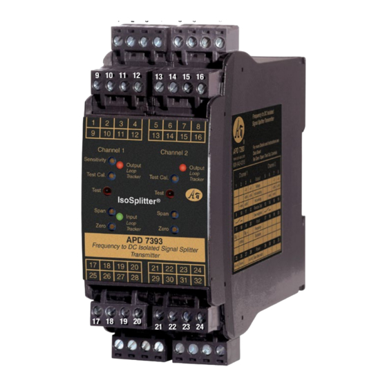
Dimensions and Connectors
1.78" W x 4.62" H x 4.81" D
45 mm W x 117 mm H x 122 mm D
Eight 4-terminal removable connectors, 14 AWG max wire size
Description
The APD 7393 IsoSplitter accepts a frequency input and
provides two optically isolated DC voltage or current outputs
that are linearly related to the input. The input range and each
output range are independent and can be specified as required.
This provides an economical solution when one signal must be
sent to two different devices.
Typical applications include isolation, output splitting, output
device separation and redundancy (i.e. to prevent failure of
the entire loop if one device fails), or a combination of these.
The input signal is filtered, amplified, split, and then passed
through an opto-coupler to the output stages. Full 4-way isola-
tion (input, output 1, output 2, power) make this module useful
for ground loop elimination, common mode signal rejection,
and noise pickup reduction.
I/O Sink/Source Versatility
Standard on the APD 7393 is a 15 VDC sensor excitation supply
for the input channel and 20 VDC loop excitation supplies for
each output channel. These power supplies can be selectively
wired for sinking or sourcing allowing use with any combina-
tion of powered or unpowered milliamp I/O devices.
How to Order
Models are factory ranged. See I/O ranges above left.
Please specify ranges and options on order
Input range
Channel 1 output range
Channel 2 output range
See options at right
Model
APD 7393
APD 7393 D
I
I
NSTRUMENTS
NSTRUMENTS
Sink or Source
mA Output for
Each Channel
9 10 11 12
Output LoopTracker
LED for Each
Channel
Adjustable Output
Test Function for
Each Channel
Zero and Span for
Each Channel
Input LoopTracker
LED
Custom I/O Ranges
Pb
Lead
Free
Connect Sink or
Source mA Input
17 18 19 20
Universal Power
Description
Power
85-265 VAC, 50/60 Hz or
IsoSplitter
60-300 VDC
1 input to
2 outputs
9-30 VDC or 10-32 VAC
1220 American Way Libertyville, IL 60048
Phone:
800-942-0315
Quick Link:
api-usa.com/7393
1
2
3
4
5
6
7
8
13 14 15 16
21 22 23 24
25 26 27 28
29 30 31 32
LoopTracker
API exclusive features include three LoopTracker LEDs (green
for input, red for each output) that vary in intensity with
changes in the process input and output signals.
These provide a quick visual picture of your process loop at all
times and can greatly aid in saving time during initial startup
and troubleshooting.
Output Test
An API exclusive feature includes output test buttons for each
channel to provide a fixed output (independent of the input)
when held depressed. A test button is provide for each output
channel. The output test greatly aids in saving time during
initial startup and/or troubleshooting.
The test output level for each channel is potentiometer adjust-
able from 0 to 100% of the output span.
Terminals are provided to operate the test functions remotely
for each channel. This also allows use as a remote manual
override to provide a temporary fixed output if desired.
Options and Accessories
Options—add to end of model number
R1
Channel 1 I/O reversal (ie. 4-20 mA in to 20-4 mA out)
R2
Channel 2 I/O reversal (ie. 4-20 mA in to 20-4 mA out)
R3
Channel 1 and channel 2 I/O reversal
M19 Channel 1 high voltage output >10 V up to 20 V
M29 Channel 2 high voltage output >10 V up to 20 V
M39 Channel 1 and channel 2 high voltage output
U
Conformal coating for moisture resistance
Accessory—order as separate line item
API BP4 Spare removable 4 terminal plug, black
api-usa.com
Fax: 800-949-7502
APD 7393
Removable Plugs
See Wiring
Diagrams on
Next Page
© 02-20
Advertisement

Subscribe to Our Youtube Channel
Related Manuals for Absolute Process Instruments IsoSplitter APD 7393


Summary of Contents for Absolute Process Instruments IsoSplitter APD 7393
- Page 1 IsoSplitter Frequency to DC Signal Splitter/Isolator/Transmitter, Factory Configured APD 7393 ® 1 Input: 0-25 Hz to 0-20 kHz Quick Link: api-usa.com/7393 2 Outputs: 0-1 V to 0-10 V, ±1 V to ±10 V, 0-1 mA to 20 mA, 4-20 mA O One Input to Two Outputs with Full Isolation Sink or Source O Zero and Span Output Calibration Potentiometers...
- Page 2 Instructions APD 7393 Precautions Removal Voltage Voltage WARNING! All wiring must be performed by a qualified electrician Avoid shock hazards! Turn signal input, output, and power off. Device 1 Device 2 or instrumentation engineer. See diagram for terminal designations 1. Push up on bottom back of module. –...
Need help?
Do you have a question about the IsoSplitter APD 7393 and is the answer not in the manual?
Questions and answers