Advertisement
Quick Links
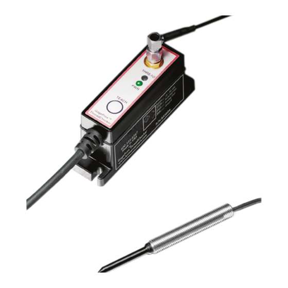
ThreadChecker
TM
Noncontact Thread Detection
System User's Manual
Copyright © 2019
Kaman Aerospace Corporation
PART NO: 860510-001A
Kaman Precision Products
Last Revised: 2019.10.22
Measuring & Memory Systems
217 Smith Street
Middletown, CT 06457
www.kamansensors.com or 860-632-4442
Page 1 of 12
Advertisement

Related Manuals for Kaman ThreadChecker


Summary of Contents for Kaman ThreadChecker
- Page 1 ThreadChecker Noncontact Thread Detection System User’s Manual Copyright © 2019 Kaman Aerospace Corporation PART NO: 860510-001A Kaman Precision Products Last Revised: 2019.10.22 Measuring & Memory Systems 217 Smith Street Middletown, CT 06457 www.kamansensors.com or 860-632-4442 Page 1 of 12...
- Page 2 EC Council Directive 89/336/EEC on the approximation of the laws of the member states relating to Electromagnetic Compatibility. Refer to the Declaration of Conformity or contact Kaman Precision Products for details. Power Supply Requirements: The power supply must be CE rated to maintain CE compliance to ESD and power surge requirements.
- Page 3 The ThreadChecker electronics uses a standard 24AWG cable to bring +15 Vdc to +30 Vdc into the electronics and provide outputs for the analog voltage and switch functions Theory of Operation The ThreadChecker system is an eddy current system.
- Page 4 The switched output can be adjusted using the teach modes. See application information for more details. Switched Output Operation The ThreadChecker’s switched output is a simple on / off switch. The switch is adjusted to trip between a 'threaded' hole and an unthreaded hole during the teach process. Cleaning The ThreadChecker is designed to have limited operation while immersed in liquids.
- Page 5 Before the system is first used it must have the ‘teach’ sequence run. In order to do this you must have a representative threaded and non-threaded hole. The system can be easily calibrated to any new sensor designed for the ThreadChecker as well as for most hole/thread configurations with a simple calibration sequence.
- Page 6 Copyright © 2019 Kaman Aerospace Corporation PART NO: 860510-001A Kaman Precision Products Last Revised: 2019.10.22...
-
Page 7: Power Led
Yellow The system is being calibrated or the button is pushed System has no power or is otherwise faulty Copyright © 2019 Kaman Aerospace Corporation PART NO: 860510-001A Kaman Precision Products Last Revised: 2019.10.22 Measuring & Memory Systems 217 Smith Street Middletown, CT 06457 www.kamansensors.com or 860-632-4442... - Page 8 There is also a limitation on very small holes (where the diameter of the hole is less than half the diameter of the sensor). Copyright © 2019 Kaman Aerospace Corporation PART NO: 860510-001A Kaman Precision Products Last Revised: 2019.10.22 Measuring &...
- Page 9 Holding switch down for longer than 10 Limits are inverted seconds (until the status light stops blinking) Copyright © 2019 Kaman Aerospace Corporation PART NO: 860510-001A Kaman Precision Products Last Revised: 2019.10.22 Measuring & Memory Systems 217 Smith Street Middletown, CT 06457 www.kamansensors.com or 860-632-4442...
- Page 10 Allow the system to warm up to operating temperature before calibrating. A full warm up usually takes about 15 minutes but usually 5 minutes is adequate. Make sure the sensor connector is screwed on tight Copyright © 2019 Kaman Aerospace Corporation PART NO: 860510-001A Kaman Precision Products Last Revised: 2019.10.22 Measuring &...
- Page 11 Electronics Mounting Instructions Mounting the ThreadChecker electronics module can be done using the two holes in the enclosure, and an M-4 (or 6-32) screw (see below). The DIN mount attachment can also be used to allow mounting on a DIN rail.
- Page 12 Electronics: 32°F to 131°F (0°C to 55°C) STORAGE TEMPERATURE RANGE Sensor and cable: -40°F to 185°F (-40°C to 85°C) Electronics: -40°F to 158°F (-40°C to 70°C) Copyright © 2019 Kaman Aerospace Corporation PART NO: 860510-001A Kaman Precision Products Last Revised: 2019.10.22 Measuring & Memory Systems...