Table of Contents
Advertisement
Quick Links
Advertisement
Table of Contents

Related Manuals for ECOTRONS ALM-BR4-4.3

Summary of Contents for ECOTRONS ALM-BR4-4.3
- Page 1 ALM Board RS485 ALM-BR4-4.3 Accurate Lambda Meter (ALM-BR4-4.3) – Mini Board Version V1.0 COPYRIGHTS ECOTRONS LLC ALL RIGHTS RESERVED www.ecotrons.com Note: If you are not sure about any specific details, please contact us at support@ecotrons.com.
- Page 2 ALM-BR4-4.3 Manual Check before you power on ALM-Board: • The oxygen sensor is installed in the right way or it's left in the free air. Make sure the environment is dry and it's not close to the inflammable materials. • The ALM-Board is correctly connected to DC power supply 12V battery.
-
Page 3: Table Of Contents
Content ALM Product Overview ....................1 ALM-Board Technical Specifications ................2 Appearance and Dimension.................... 3 3.1 Appearance picture ....................... 3 3.2 Dimensions (Unit: mm) ......................4 Oxygen Sensor Protection ....................5 ALM-Board Operating Instructions ................. 6 5.1 Pin Assignment ........................6 5.2 Communication Protocol for RS485 Bus ................ -
Page 4: Alm Product Overview
ALM-BR4-4.3 Manual ALM Product Overview ALM (Accurate Lambda Meter) is an air-fuel-ratio (AFR) meter that uses the Bosch LSU 4.9 wideband oxygen sensor and Bosch semiconductor chip CJ125 to accurately measure the AFR or lambda for variant combustion engines. ALM-Board is a version of ALM that trims off the peripheral parts and keeps the minimum set of electronics yet providing the core function of the wideband controller. -
Page 5: Alm-Board Technical Specifications
ALM-BR4-4.3 Manual ALM-Board Technical Specifications Power supply ◆ Input voltage range DC12V (typical value), DC 10V ~15V ◆ Input current 60mA typical for the board; the heater current directly from 12V supply Sensors ◆ Standard configuration LSU 4.9 ◆ Also support LSU ADV (software configuration needed) ◆... -
Page 6: Appearance And Dimension
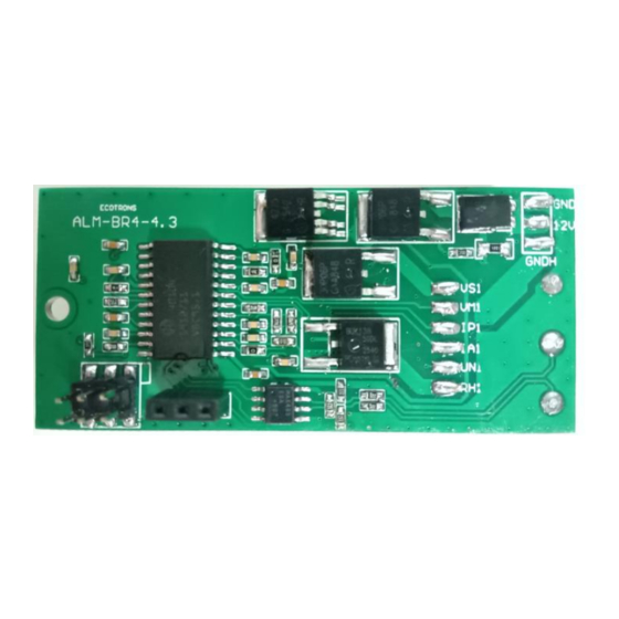
ALM-BR4-4.3 Manual Appearance and Dimension 3.1 Appearance picture Copyrights ECOTRONS LLC www.ecotrons.com... -
Page 7: Dimensions (Unit: Mm)
ALM-BR4-4.3 Manual 3.2 Dimensions (Unit: mm) Copyrights ECOTRONS LLC www.ecotrons.com... -
Page 8: Oxygen Sensor Protection
ALM-BR4-4.3 Manual Oxygen Sensor Protection Installation The correct installation of the oxygen sensor is a must to avoid sensor damage. It protects the oxygen sensor from condensations and gives the sensor a longer life. It can also make the measurement more accurate. The sensor body should be perpendicular... -
Page 9: Alm-Board Operating Instructions
ALM-BR4-4.3 Manual ALM-Board Operating Instructions 5.1 Pin Assignment Copyrights ECOTRONS LLC www.ecotrons.com... -
Page 10: Communication Protocol For Rs485 Bus
RS-485 Communication Ground (Reference ground) 5.2 Communication Protocol for RS485 Bus RS485 communication is based on Modbus protocol. Ecotrons Modbus protocol uses ASCII and RTU mode and supports PLC, DTC, etc. More details refer to ALM Communication Protocol – SCI.doc http://www.ecotrons.com/download/... - Page 11 ALM-BR4-4.3 Manual PLC to ALM, PLC sends: "50 03 2000 0004 42 48" Resolution Units Range ALM to PLC, PLC receives: "50 03 08 xxxx xxxx xxxx xxxx xxxx" PLC to ALM Request Data(byte) Description Registers Start Addr Hi for sent...
- Page 12 ALM-BR4-4.3 Manual 0.000244 Temperature Temperature = High 8-bit ((LSU Temperature High 8- 840 to bit)*256 + 1303 (LSU Temperature Temperature Low 8-bit High 8-bit)) * 0.023438 Faults LSU Sensor High 8-bit faults = ((LSU Faults High 8- 0 to bit) *256+(LSU...
-
Page 13: How To Communicate To Alm Gui
ALM-BR4-4.3 Manual How to Communicate to ALM GUI The 3-pin connector in the picture above is only used for flashing the S19 file. And that is RS232 bus. The ModBUS or RS485 communication must be through the regular port “A” and “B”... -
Page 14: How To Flash The S19 File
ALM-BR4-4.3 Manual How to Flash the S19 File In the above picture, part 1 is connected to the computer; In the above picture, part 2 is connected to the 3-pin connector of the ALM board. Note: The MAX 232 adapter and USB-RS232 converter are optional, and they are not included in the standard ALM-Board kits. -
Page 15: Alm Gui For Modbus
ALM-BR4-4.3 Manual Step 1: In the settings, set the communication mode to USB Step 2: Click <Open file> to select and load the S19 file Step 3: Click <Flash> Step 4: You will see the alert on the bottom of the window to power off the ECU and then power on. -
Page 16: Dtc Table
ALM-BR4-4.3 Manual DTC Table Below is the Diagnostic Trouble Code table. ALM-Board has on-board-diagnostics capability to detect most of the common errors. The first thing user should do when ALM-Board is not working properly is to read DTCs. Trouble Code...
Need help?
Do you have a question about the ALM-BR4-4.3 and is the answer not in the manual?
Questions and answers