Advertisement
Quick Links
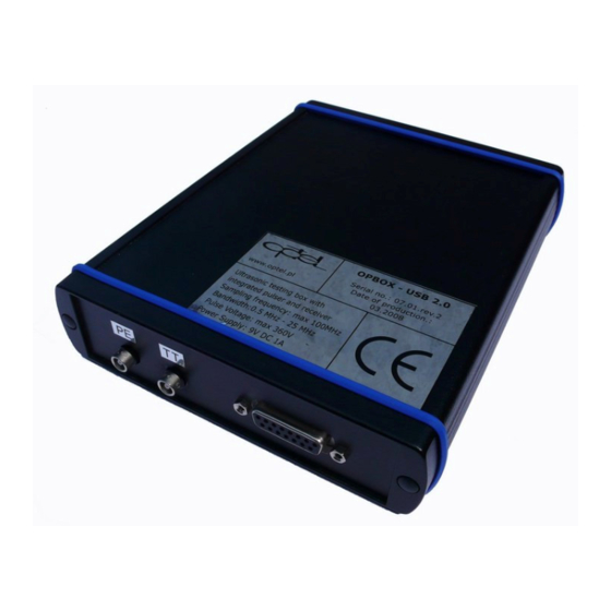
Ultrasonic box with integrated pulser and receiver rev. 3
OPBOX - USB 2.0 is a complete ultrasonic testing device, suitable for all ultrasonic
measurements, and due to many additional inputs and outputs, it can be used as a controller
for more complicated devices.
The box can work together with following
devices:
2 - 32 channel multiplexer - the
•
OPBOX can control it directly;
Scanner - it has input for incremental
•
encoders;
The box contains one channel pulser &
receiver and can be used with one
transducer or with two (one is sending and
the second receiving) for pulse-echo and
through transmission measurements.
Size: 164mm x 138mm x 34 mm
Power Supply: 9V DC / 2A
Technical data
A/D converter:
- Resolution:
- Sampling frequency:
Delay time:
Data buffer:
Analog parameters
- Input amplifier gain:
- Input preamplifier
- Sensitivity:
- Bandwidth:
- Input impedance
- Filters switchable
Przedsiębiorstwo Badawczo-Produkcyjne
OPBOX - USB 2.0
8 bit (internal 10bits)
12.5, 25, 50 or 100MHz
Post trigger 256µs
256, 512, 1k, 2k,4k,8k,16k, 32k, 64k, 128kB
from -29dB to 67dB
0dB or +24dB
0.1mV - 1Vpp
0.5 MHz - 25 MHz (-3dB)
50 Ohm, 10pF
1
0.5 – 6MHz
, 0.5 – 10MHz
1
1 – 6MHz
, 1 – 10MHz
1
2 – 6MHz
, 2 – 10MHz
1
4 – 6MHz
, 4 – 10MHz
OPTEL Sp. z o.o.
ul. Morelowskiego 30
PL-52-429 Wrocław
tel.: +48 (071) 329 68 54
fax.: +48 (071) 329 68 52
e-mail: optel@optel.pl
http://www.optel.pl
Wrocław, 21.05.2008
1
1
1
, 0.5 – 15MHz
, 0.5 – 25MHz
1
1
, 1 – 15MHz
, 1 – 25MHz
1
1
, 2 – 15MHz
, 2 – 25MHz
1
1
, 4 – 15MHz
, 4 – 25MHz
1
1
,
1
,
1
,
1
Advertisement

Summary of Contents for optel OPBOX
- Page 1 OPBOX - USB 2.0 Ultrasonic box with integrated pulser and receiver rev. 3 OPBOX - USB 2.0 is a complete ultrasonic testing device, suitable for all ultrasonic measurements, and due to many additional inputs and outputs, it can be used as a controller for more complicated devices.
- Page 2 DAC (TGC) with arbitrary waveform generator - Resolution of time step 0.05 ms - Resolution 8 bit - Max. Gain changing 48dB pro step Counters / Input for incremental encoder: - Counters for Incremental 8-bit Encoders 2 channel Trigger - Internal trigger rate Software - External trigger rate TTL Signal...
- Page 3 Green – USB connected Characteristic of the box One of the most important features of the OPBOX – USB 2.0 is a synchronization between the pulser signal and the internal clock, that controls the A/D converter. This allows very precise measurements of the time of flight –...
- Page 4 1. Connect OPBOX – USB 2.0 to the Power Supply 2. Connect OPBOX – USB 2.0 to the PC. Because USB is hot pluggable, Windows should be able to detect OPBOX – USB 2.0, and the Add New Hardware Wizard should open automatically as soon as you connect it to the USB port.
- Page 5 PLEASE select USB low driver. 4. Reboot your computer. 5. START-> OPBOX – USB 2.0 -> opbox.exe Control Panel -> Hardware Manager. NI-VISA USB Devices -> OPBOX – USB 2.0 s.7.0. rev 0.3...
- Page 6 Features of the OPBOX – USB 2.0 s.7.0. rev 0.3 – Each devices has unique serial number – i.e. SN 07.04 rev.2 Description of control function OPBOX – USB 2.0 List of function includes on viopbox.dll Sample_OpenOpbox Sample_CloseOpbox Sample_ResetOpbox Sample_Set_PreAmp...
- Page 7 Sample_StartRUN Sample_StopRUN Sample_StartSINGLE Sample_SendTGC Basic control functions: Function Description DLL Command Sample_OpenOpbox Open driver for OPBOX – int Sample_OpenOpbox (void); USB 2.0 Return: 0 – success -1 – error Sample_CloseOpbox Close driver void Sample_CloseOpbox (void); Sample_ResetOpbox Reset – restart the devices void Sample_ResetOpbox (void);...
- Page 8 8 - 2 – 6MHz, 9 - 2 – 10MHz, 10 - 2 – 15MHz, 11 - 2 – 25MHz, 12 - 4 – 6MHz, 13 - 4 – 10MHz, 14 - 4 – 15MHz, 15 - 4 – 25MHz; Sample_Set_TPuls Set impulse length void Sample_Set_TPuls (double tpuls);...
- Page 9 Sample_Set_Delay Set post trigger delay void Sample_Set_Delay(int hdelay); Parameter: hdelay from 0 to 255 Sample_Set_Depth Set length bulk transfer void Sample_Set_Depth(double rating); Parameter: rating – from 1 to 131072 Sample_StopBulk Stop bulk transfer void Sample_StopBulk (void); Sample_StartBulk Open memory channel for void Sample_StartBulk (void);...
- Page 10 Standard software OPBOX – USB 2.0 software rev. 0.9 2008 @ PBP OPTEL sp. z o.o. http://www.optel.pl Main Panel Overview of Hotkey Selection: Hotkey Function F1 STOP/START enables / disables selected acquisition mode – start /stop measurement F2 Load Settings...
- Page 11 Settings on the main panel Function Pulser Ampl - Set impulse voltage from off to 360V range in 13 levels Pulser Time - Set impulse length from 0us to 3.1us (step 0.1us) Mode - PE – Measured input signal (sending/receiving); TT – Measured input signal (receiving) Channel - This function allows choosing the channel, if multiplexer is used.
- Page 12 Measurement Gates Using cursors it is possible to set two measurement gates in which different functions can be performed. In the part of the main screen, visible here the positions of this gates and the maximum amplitude, attenuation, phase of signal is shown.
- Page 13 and physics of ultrasounds. The next step is to choose (toggle button “V”), if thickness or sound velocity should be measured. Than it is necessary to mark, which value should be used as constant. The remaining value will be calculated. The information from the window Ref.
- Page 14 Bottom window features zoom Upper window – yellow trace of the measurement signal – with two measurement gates (white and blue) and the third red cursor for the zoom with is displayed on the bottom window. Bottom window – with zoom of the measurement signal choosing by red cursor on the upper window FFT windowed This function shows the real part of the FFT (with Hamming window applied) of the whole...
- Page 15 FFT cursors This function shows the real part of the FFT (with Hamming window applied) of the signal, shown on the upper window in the region, embraced by the gate, that appears on the upper window in this mode (red on the above picture). Additional features are available: Frequency [MHz] - Domain frequency is shown.
- Page 16 Amplification of the received signal and gain curve (TGC function) The OPBOX has not only a simple amplifier, but a special function, allowing amplifying the signal depending on the time, passed from the start (trigger). This function is called time-gain compensation (TGC).
- Page 17 To draw the curve, the user must click on Acquire, after the curve is ready on Done and Set, and the transfer of the curve to the card is fulfilled with set. Protocol Panel – under F8 Protocol...
- Page 18 Overview of Hotkey Selection: Hotkey Function F1 Run Periodical Periodical Measurement with adjusted interval and cycle length F2 Run Standard measurement with speed what fast computer can F5 Sequence It is also possible to decide, if the information from different channels should be added (to produce for example one spectrum information from many channels) or treated as a sequence (each channel is separated).
- Page 19 Exit from the OPBOX – USB 2.0 software: When the OPBOX software is to be closed last panel is displayed. If the settings should be saved then OPBOX software will start with this settings. EXAMPLE OF MEASUREMENTS WITH THE OPBOX For better understanding we have prepared an example, showing the use of OPBOX.
- Page 20 Fig.2 Measurement of parameters: time of flight, sound speed, distance, using pulse echo (PE) method. First such parameters as window, delay, gain – depending on the measured object must be set and naturally the mode (PE). Now we must set the gates so, that the signal reflected from the wall is inside (first and the second reflection) –...
- Page 21 Fig.4 Measurement of parameters: time of flight, sound speed, distance, using TT method First such parameters as window, delay, gain – depending on the measured object must be set and naturally the mode (TT). Now we must set the gates so, that the signal transmitted and reflected from the wall is inside (first and the second reflection) –...
- Page 22 Fig. 6 Measurement with delay lines. This is possible with the function “pattern”. It allows to exclude automatically the transmission time through the delay line from the calculations. For this purpose it is first necessary to measure time of flight through the delay line. Than the measured signal should be stored as pattern.
- Page 23 If you have any question, please do not hesitate to contact us. PBP Optel Spółka z o.o.zarejestrowana w Rejestrze Przedsiębiorców przez Sąd Rejonowy dlaWrocławia Fabrycznej VI Wydział Gospodarczy Krajowego Rejestru Sądowego pod nr KRS 0000124439.
Need help?
Do you have a question about the OPBOX and is the answer not in the manual?
Questions and answers