Table of Contents
Advertisement
Available languages
Available languages
Quick Links
Advertisement
Table of Contents

Related Manuals for Signature Kitchen Suite SKSPH4802S


Summary of Contents for Signature Kitchen Suite SKSPH4802S
- Page 1 INSTALLATION GUIDE HOOD Read these instructions thoroughly before installing and operating the hood. SKSPH3602S SKSPH4802S www.signaturekitchensuite.com Copyright © 2017 - 2018 Signature Kitchen Suite. All Rights Reserved. MFL70208703_01...
-
Page 2: Table Of Contents
TABLE OF CONTENTS TABLE OF CONTENTS BEFORE YOU BEGIN 14 INSTALLATION INSTRUCTIONS Rotating the Blower Mounting the Range Hood IMPORTANT SAFETY INSTRUCTIONS 17 WIRING DIAGRAM PRODUCT SPECIFICATIONS General Specifications Dimensions PRODUCT OVERVIEW Parts Accessories 10 PLANNING THE INSTALLATION Cabinet Layout Ducting Options Ducting Calculation Sheet Power Supply... -
Page 3: Before You Begin
It is located inside the hood behind the filters on the back side of the chassis. Remove the filters to view it. All specifications subject to change without notice. SIGNATURE KITCHEN SUITE assumes no liability for changes to specifications. -
Page 4: Important Safety Instructions
IMPORTANT SAFETY INSTRUCTIONS IMPORTANT SAFETY INSTRUCTIONS Read and follow all instructions when using the range to prevent the risk of fire, electric shock, personal injury, or damage. This guide does not cover all possible conditions that may occur. Always contact your service agent or manufacturer about problems that you do not understand. - Page 5 IMPORTANT SAFETY INSTRUCTIONS WARNING TO REDUCE THE RISK OF FIRE, ELECTRIC SHOCK, OR INJURY TO PERSONS, OBSERVE THE FOLLOWING: – Installation work and electrical wiring must be done by qualified person(s) in accordance with all applicable codes and standards, including fire-rated construction. –...
- Page 6 IMPORTANT SAFETY INSTRUCTIONS WARNING Never allow the filter(s) to become blocked or clogged. Do not allow foreign objects, such as cigarettes or napkins, to be sucked into the hood. Clean the filter(s) and all grease-laden surfaces often to prevent grease fires and maintain performance.
-
Page 7: Product Specifications
Fan Speeds Filters Baffle type, dishwasher safe Total Connect Load 120 VAC, 60 Hz, 4 Amp. Lights 120 VAC, 8 W LED light strip Model Number SKSPH4802S SKSPH3602S Filters Model Number Weight SKSPH4802S 71 lb. (32.5 kg) SKSPH3602S 60 lb. (27.2 kg) -
Page 8: Dimensions
18" " " " " 4" 24" * Single Blower Rect. Ducting Dimension ** Single Blower Round Ducting Dimension *** Dual Blower Dimension Back Dimensions " " " Overall Dimensions Model SKSPH4802S 48" " 18" 24" 6" SKSPH3602S 36" "... -
Page 9: Product Overview
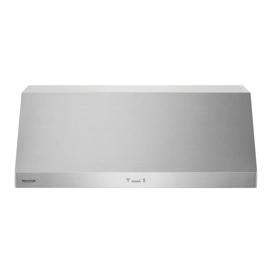
PRODUCT OVERVIEW PRODUCT OVERVIEW Parts 1 HOOD 3 LED STRIP LIGHT 2 ICON TOUCH CONTROL PANEL 4 BAFFLE FILTER (SKSPH4802S: 4pcs, SKSPH3602S: 3pcs) Accessories Included Accessories Manual 8" round collar Top cover plate 3 1/4"x10" Manual rectangular duct collar M6 x 1" (4) M6 x 1-1/2"... -
Page 10: Planning The Installation
Minimum Cabinet Width customer. Models Width If the unit is damaged by the installer (if other than the customer), repair or replacement must SKSPH4802S 48" (121.9 cm) be made by arrangement between customer SKSPH3602S 36" (91.5 cm) and installer. -
Page 11: Ducting Options
PLANNING THE INSTALLATION Ducting Options WARNING Fire Hazard NEVER exhaust air or terminate duct work into spaces between walls, crawl spaces, ceiling, attics or garages. All exhaust must be ducted to the outside. Rear Ducting Use metal ductwork only. Fasten all connections with sheet metal screws and tape all joints with certified Silver Tape or Duct Tape. -
Page 12: Ducting Calculation Sheet
12 PLANNING THE INSTALLATION Ducting Calculation Sheet Duct pieces Equivalent Total Duct pieces Equivalent Total length x number length x number used used 3-1/4" x 10" 1 Ft. 6" Round 30 Ft. Rect., wall cap straight with damper 6" Round, 1 Ft. -
Page 13: Power Supply
PLANNING THE INSTALLATION Ductwork Design Tips Electrical Supply Wherever possible, reduce the number of transitions This appliance requires a 120V 60Hz electrical and turns to as few sharp angles as possible. Two supply, and must be connected to an individual, staggered 45°... -
Page 14: Installation Instructions
14 INSTALLATION INSTRUCTIONS INSTALLATION Rotating the Blower INSTRUCTIONS This range hood is equipped standard with a 8” round vertical duct option. To convert from 8” round vertical to 8” round horizontal ducting or 3-1/4” x 10” WARNING rectangular horizontal ducting please following the instructions below. - Page 15 INSTALLATION INSTRUCTIONS Remove the 4 screws holding the blower to the From inside the hood body, align the top cover blower plate. Turn the blower 180 degrees and plate to the top of the hood body. Attach the top reattach it to the blower plate. cover plate from the outside of the hood, using four 3/16"...
-
Page 16: Mounting The Range Hood
M6 wood screws. Wood Board Dimensions : (W x D x H) FIG. 1 SKSPH3602S - 33" x 1/2" x 4" SKSPH4802S - 45" x 1/2" x 4" " Prepare the duct pipe and duct cutouts in "... -
Page 17: Wiring Diagram
WIRING DIAGRAM WIRING DIAGRAM Models Volts MAX Amps Single Motor 4 SKSPH4802S SKSPH3602S Dual Motor 7 WHITE WHITE GRAY GRAY BROWN BROWN BLUE BLUE YELLOW YELLOW GREEN GREEN MOTOR MOTOR AC N AC L BODY TRANSFORMER Wi-Fi PCB Wi-Fi PCB... - Page 18 18 MEMO MEMO...
- Page 19 GUÍA DE INSTALACIÓN CAMPANA Lea atentamente estas instrucciones antes de instalar y poner la campana en funcionamiento. SKSPH3602S SKSPH4802S www.signaturekitchensuite.com Copyright © 2017 - 2018 Signature Kitchen Suite. Todos los Derechos Reservados. MFL70208703_01...
- Page 20 ÍNDICE ÍNDICE ANTES DE COMENZAR 14 INSTRUCCIONES DE INSTALACIÓN Posicionamiento del extractor Montaje de la campana extractora INSTRUCCIONES IMPORTANTES DE SEGURIDAD 17 DIAGRAMA DE CABLEADO ESPECIFICACIONES DEL PRODUCTO Especificaciones generales Dimensiones DESCRIPCIÓN GENERAL DEL PRODUCTO Piezas Lista de piezas 10 PLANIFICACIÓN DE LA INSTALACIÓN Disposición de alacenas Opciones de conducto Hoja de cálculo de conducto...
- Page 21 ANTES DE COMENZAR ANTES DE COMENZAR IMPORTANTE: Instalador: Para preservar la seguridad y reducir los posibles problemas, lea estas instrucciones para la instalación por completo antes de comenzar el proceso de instalación. Deje estas instrucciones al cliente. Cliente: Conserve estas instrucciones de instalación para referencia futura y para que las consulte el inspector PLACA DE DATOS DEL ARTEFACTO La placa de datos de este artefacto contiene información del número de serie y el modelo, y los...
- Page 22 INSTRUCCIONES IMPORTANTES DE SEGURIDAD INSTRUCCIONES IMPORTANTES DE SEGURIDAD Lea y siga todas las instrucciones cuando utilice la cocina para evitar riesgos de incendios, descargas eléctricas, lesiones personales o daños. Esta guía no incluye todas las situaciones posibles que podrían ocurrir. Siempre comuníquese con su agente de servicio técnico o con el fabricante cuando haya problemas que no comprenda.
- Page 23 INSTRUCCIONES IMPORTANTES DE SEGURIDAD ADVERTENCIA PARA REDUCIR EL RIESGO DE INCENDIO, DESCARGAS ELÉCTRICAS O LESIONES PERSONALES, TENGA EN CUENTA LO SIGUIENTE: – El trabajo de instalación y el cableado eléctrico deben ser realizados por personal calificado en conformidad con todos los códigos y las normas aplicables, incluso respecto a construcciones a prueba de fuego.
- Page 24 INSTRUCCIONES IMPORTANTES DE SEGURIDAD ADVERTENCIA Lea el manual del propietario por completo antes de usar el aparato. Limpie el aparato solamente como se indica en el manual del propietario. Use únicamente los productos de limpieza especificados. No manipule indebidamente los controles. Nunca permita que el/los filtro(s) se bloquee(n) u obstruya(n).
- Page 25 Tipo deflector, aptos para lavavajillas Carga total de conexión 120 V CA, 60 Hz, 4 A. Luces 120 V CA, tira de luces LED de 8 W Número de modelo SKSPH4802S SKSPH3602S Filtros Número de modelo Peso SKSPH4802S 71 lb (32,5 kg)
- Page 26 " " 4" 24" * Dimensión ventilador individual de rectangular ** Dimensión ventilador individual de redondo *** Dimensión ventilador doble Dimensiones de la parte posterior " " " Dimensiones generales Modelo SKSPH4802S 48" " 18" 24" 6" SKSPH3602S 36" "...
- Page 27 DESCRIPCIÓN GENERAL DEL PRODUCTO Piezas 1 CAMPANA 3 LUZ LED 2 PANEL DE CONTROL TÁCTIL CON ICONOS 4 FILTRO DEFLECTOR (SKSPH4802S: 4 pzas., SKSPH3602S: 3 pzas.) Lista de piezas Accesorios incluidos Manual Collarín redondo 8" Placa de cubierta superior collarín de conducto Manual rectangular 3 1/4"x10"...
- Page 28 Si la unidad ha sido dañada por el instalador (si es Modelos Ancho distinto al cliente), la reparación o sustitución debe SKSPH4802S 48" (121,9 cm) realizarse mediante acuerdo entre el cliente y el instalador. SKSPH3602S 36" (91,5 cm)
- Page 29 PLANIFICACIÓN DE LA INSTALACIÓN Opciones de conducto ADVERTENCIA Riesgo de fuego NUNCA extraiga aire o termine el conducto en espacios entre paredes, espacios angostos, techos, áticos o garajes. Toda la extracción debe realizarse al exterior. Conducto trasero Utilice únicamente conductos de metal. Fije todas las conexiones con tornillos para metal y cubra todas las juntas con cinta plateada o cinta de conducto certificada.
- Page 30 12 PLANIFICACIÓN DE LA INSTALACIÓN Hoja de cálculo de conducto Piezas de conducto Longitud Total Piezas de conducto Longitud Total equivalente x equivalente x número usado número usado Rectangular, 1 Ft. x ( ) = 6" tope de 30 Ft. x ( ) = recto pared redondo...
- Page 31 PLANIFICACIÓN DE LA INSTALACIÓN Consejos para el diseño del conducto Suministro eléctrico Siempre que sea posible, reduzca el número de Este aparato requiere un suministro eléctrico de 120V transiciones y curvas al menor número de ángulos agudos 60Hz, y debe conectarse a un circuito ramal con una que sea posible.
- Page 32 14 INSTRUCCIONES DE INSTALACIÓN INSTRUCCIONES DE Posicionamiento del extractor INSTALACIÓN Esta campana extractor está equipada de forma estándar con una opción de conducto vertical redondo de 8". Para convertir el conducto vertical redondo de 8" a un conducto ADVERTENCIA horizontal redondo de 8" o un conducto rectangular horizontal de 3-1/4"...
- Page 33 INSTRUCCIONES DE INSTALACIÓN Quite los 4 tornillos que sujetan el soplador a la placa Desde el interior del cuerpo de la campana, alinee la del soplador. Gire el soplador 180 grados y vuelva a placa superior con la parte superior del cuerpo de la ajustarlo a la placa del soplador.
- Page 34 (Ancho x Profundidad x Altura) " SKSPH3602S - 33" x 1/2" x 4" " SKSPH4802S - 45" x 1/2" x 4" Prepare el tubo de conducto y los cortes de conducto en el armario superior si fuera necesario, o en la "...
- Page 35 DIAGRAMA DE CABLEADO DIAGRAMA DE CABLEADO Modelos Voltios Amps Máx. Motor individual 4 SKSPH4802S SKSPH3602S Motor doble 7 WHITE WHITE GRAY GRAY BROWN BROWN BLUE BLUE YELLOW YELLOW GREEN GREEN MOTOR MOTOR AC N AC L BODY TRANSFORMER Wi-Fi PCB...
- Page 36 Customer Information Center For inquires or comments, call: 1-855-790-6655 USA...
Need help?
Do you have a question about the SKSPH4802S and is the answer not in the manual?
Questions and answers