Table of Contents
Advertisement
Quick Links
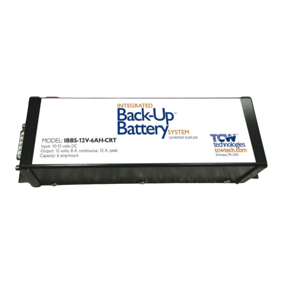
Integrated Back-up Battery System
Model: IBBS-12v-6ah-CRT
The Integrated Back-up Battery System, IBBS, is an electronic system
that combines a Lithium-Iron-Phosphate (Li-Fe-PO4) battery pack, a
charger and switching logic in one convenient package. The IBBS
provides an engineered solution to enable an endurance bus for critical
loads found in aircraft. It simplifies the wiring and installation of a source
of back-up power by integrating all of the key elements in a single
enclosure. The IBBS system provides back-up power to critical
electronic loads such as EFIS, GPS, Autopilots, Radios and engine
monitor systems.
Integral to the IBBS is a lithium-iron-phosphate battery pack and a
matched charging system to ensure the battery is properly charged and
maintained. The system also includes switching circuitry to provide a
stable source of output power during normal and emergency operations.
The IBBS system also provides signals to other equipment such as EFIS
systems to communicate the operating state of the main aircraft bus as
well as the state of the battery.
The IBBS system connects to the standard aircraft power bus and
provides outputs to critical equipment that require back-up power.
Additionally, the IBBS system provides surge and sag protection for
p/n 725.0001 REV 1.5
© 2021 TCW Technologies, LLC.
1
Advertisement
Table of Contents

Related Manuals for TCW IBBS-12v-6ah-CRT

Summary of Contents for TCW IBBS-12v-6ah-CRT
- Page 1 The IBBS system connects to the standard aircraft power bus and provides outputs to critical equipment that require back-up power. Additionally, the IBBS system provides surge and sag protection for p/n 725.0001 REV 1.5 © 2021 TCW Technologies, LLC.
-
Page 2: Table Of Contents
13 Connector Pin-out pg. 14 Mounting plate drawing pg. 15 General Wiring diagram pg. 16 Example Wiring diagrams pg. 17-18 Environmental Qualification Statement pg. 19 Support and Warranty information pg. 20 p/n 725.0001 REV 1.5 © 2021 TCW Technologies, LLC. -
Page 3: Limitations
The preferred operating temperature range of the system is -40 C° to 60 C°, the effective charging temperature range is -40 C° to 40 C° with extended charging times below 0 C°. Select an installation location that takes these temperatures into consideration. p/n 725.0001 REV 1.5 © 2021 TCW Technologies, LLC. - Page 4 Pin 5. Output Power connections: The IBBS-12v-6ah-CRT has four output pins, Pins 12,13,14,15. These pins provide power to the connected load. These four wires may be paralleled together for redundancy and load current sharing. Use 20 awg wire for each pin. The total combined load for all four pins is 8 amps continuous, 12 amps peak.
-
Page 5: General Product Information
IBBS when using the IBBS to power an electronic ignition module. Do not use the IBBS system to back-up a dual ignition system having only a single power input. Do not use a single IBBS system to back-up two electronic ignition systems. p/n 725.0001 REV 1.5 © 2021 TCW Technologies, LLC. - Page 6 See page 5 for details on battery charging time. If voltage monitoring of pin 2 of the IBBS is available a peak charging voltage of 14-15 volts will be observed as the battery reaches full capacity. p/n 725.0001 REV 1.5 © 2021 TCW Technologies, LLC.
-
Page 7: Battery Capacity Details
The internal battery in the IBBS system is replaceable; however, the IBBS product must be returned to TCW Technologies, LLC. for this service. Battery life depends strongly on many factors including operating and storage temperature, number of discharge cycles and depth of discharge. -
Page 8: Product Operation
1) Operate the Aircraft Master Power Switch per the Emergency Procedure checklist already established for the aircraft. 2) Ensure the Back-up Master Switch is in the ON position. 3) Land aircraft as soon as practical to resolve the loss of main electrical power. p/n 725.0001 REV 1.5 © 2021 TCW Technologies, LLC. -
Page 9: Instructions For Continued Airworthiness
On at least an annual basis the endurance capability of the IBBS system shall be confirmed and compared against the back-up endurance required for the connected equipment. As an alternate to these tests, the IBBS unit may be returned to TCW Technologies for a loaded endurance test, contact TCW Technologies LLC. for details. - Page 10 30 minutes, whichever is greater. As an alternate to these tests the IBBS unit may be returned to TCW Technologies for a loaded endurance test, contact TCW for details.
- Page 11 Operational performance must be checked at least annually per the requirements for continued airworthiness listed above. At the end of 72 months of service installation the internal battery pack must be replaced. p/n 725.0001 REV 1.5 © 2021 TCW Technologies, LLC.
-
Page 12: Specifications
*minimum input voltage to start a charge cycle is 13.7 volts, this ensures aircraft alternator is running prior to starting a charge cycle **transition voltage is the voltage level on the input (pin 5) that causes the system to provide output power via the internal back-up battery p/n 725.0001 REV 1.5 © 2021 TCW Technologies, LLC. -
Page 13: Functional Performance, Environmental Testing
14 volts nominal, 3.3 amps charging, 1.4 amps heating Power Output 12.8 volts nominal, 8 amps continuous Battery capacity 5.5 amp-hrs at 1C rate @ 25 C° Maintenance Perform annual capacity check p/n 725.0001 REV 1.5 © 2021 TCW Technologies, LLC. -
Page 14: Connector Pin-Out
Low Volt Warn Pwr +, battery heater PWR + in, charge, sensing Pwr +, pass-thru input Pwr +, pass-thru input Pwr +, pass-thru input Ground Ground Ground Output Output Output Output p/n 725.0001 REV 1.5 © 2021 TCW Technologies, LLC. -
Page 15: Mounting Plate Drawing
Product mounting footprint 7.70 4 mounting holes. 0.190 Top View 1.50 2.290 7.25 0.225 All dimensions in inches Product height = 2.75” C.G at center of all axis p/n 725.0001 REV 1.5 © 2021 TCW Technologies, LLC. -
Page 16: General Wiring Diagram
Ground Low Volt Warn Ground PWR + in, battery heater Output PWR + in, charge, sensing Output Pwr +, pass-thru input Output Pwr +, pass-thru input Output Pwr +, pass-thru input p/n 725.0001 REV 1.5 © 2021 TCW Technologies, LLC. -
Page 17: Example Wiring Diagrams
Master Solenoid Example wiring for systems without back-up power inputs NOTE: Use redundant ground pins 9,10,11 Use redundant power inputs 6,7,8 Battery based on load current of connected equipment p/n 725.0001 REV 1.5 © 2021 TCW Technologies, LLC. - Page 18 2) Use redundant power inputs 6,7,8 based on load current of connected equipment. 3) Use of power pins will power connected equipment even when avionics bus is OFF via pass thru mode. Use of input pins 6,7,8 is OPTIONAL. p/n 725.0001 REV 1.5 © 2021 TCW Technologies, LLC.
-
Page 19: Environmental Qualification Statement
Category TT Emission of RF energy Category M lightning environment * Category A3H3L3 level 3 lightning direct Category X icing Category X Category A flammability Category X RTCA DO-160 F,G B2BBBSC1XYXXFSZB(IX)XXXXAZ(ZC)[TT]MA3H3L3XXAX p/n 725.0001 REV 1.5 © 2021 TCW Technologies, LLC. -
Page 20: Support And Warranty Information
Damage due to equipment, environment or conditions beyond the control of TCW Technologies are NOT COVERED BY THIS WARRANTY. LABOR, COSTS: TCW shall IN NO EVENT be responsible or liable for the cost of field labor or other charges incurred by any customer in removing and/or reaffixing any TCW product, part or component thereof.
Need help?
Do you have a question about the IBBS-12v-6ah-CRT and is the answer not in the manual?
Questions and answers