
Summary of Contents for ATN CX 12
- Page 1 Lieu Dit Bacqué – rue André Thévet 47400 FAUILLET- FRANCE Tel.: 33 (0)5 53 79 83 20 Fax: 33 (0)5 53 79 96 90 e-mail: contact@atnplatforms.com Operator and Safety Manual CX 12 - CX 15 11/2009 1NO 0027EN-01 1NO0031EN-08 revision 06/2018...
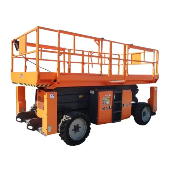
- Page 2 OPERATOR AND SAFETY MANUAL DISTRIBUTOR'S STAMP 1NO0031EN-08 CX 12 - CX 15...
- Page 3 The information in this manual does not, in any case, replace community, state, local regulations or safety instructions or insurance policy requirements Due to constant improvements made to its products, ATN reserves the right to alter their specifications and equipment without prior notice.
- Page 4 DRIVE WITH PLATFORM ELEVATED THIS TYPE OF MACHINE. WHILE ON SLOPES, UNEVEN OR SOFT SURFACES. UNTRAINED OPERATOR PUTS WHEELS HIMSELF AND OTHERS AT RISK OF OUTRIGGERS) MUST REMAIN DEATH OR SERIOUS INJURIES. PERMANENT CONTACT WITH THE GROUND. 1NO0031EN-08 CX 12 - CX 15...
- Page 5 If the distributor is unknown or cannot be informed, please contact: Tel: 33 (0)5 53 79 80 60 Fax: 33 (05) 53 79 96 90 Address: Lieu Dit Bacqué, rue André Thévet, 47400 Fauillet, France 1NO0031EN-08 CX 12 - CX 15...
- Page 6 It also meets appropriate provisions, such as directive CEM 2004/108/CE of 15 December 2004 and directive 2000/14/CE of 8 may 2000. Sound Power level : 104dB The CE type certificate was issued by: APAVE 13 to 17 rue Salneuve 75854 PARIS CEDEX 17 Under reference: 0060/5253/760/08/17/0013 1NO0031EN-08 CX 12 - CX 15...
-
Page 7: Table Of Contents
8.1. HOME SCREEN ................................46 8.2. MENUS ................................... 47 8.3. SETTINGS ..................................53 8.4. ACCESSING THE IQAN "DEFAULT VALUES" PAGE ..................... 54 Section 9. DIAGRAMS ................................56 9.1. ELECTRIC SCHEMATIC .............................. 56 9.2. HYDRAULIC SCHEMATIC ............................59 CX 12 - CX 15 1NO0031EN-08... -
Page 8: Section 1. General Description
Extension avant Rear deck extension Extension arrière REAR FRONT ARRIERE AVANT Outriggers Stabilisateurs Stabilisateurs Outriggers Rear axle Essieu avant Essieu arrière Réservoir Blocs Steering/oscillating Hydraulic Hydraulic fluid hydraulique hydrauliques directeur/oscillant front axle manifolds reservoir 1NO0031EN-08 CX 12 - CX 15... -
Page 9: Features - Dimensions
LEVELLING CAPACITY – FRONT TO BACK LEVELLING CAPACITY – SIDE TO SIDE CAPACITE DE MISE A NIVEAU LONGITUDINALE CAPACITE DE MISE A NIVEAU TRANSVERSALE Model Modèle CX12 CX12 Dimensions in Dimensions metres (m) en mètres (m) 5.5° 9.4° 1NO0031EN-08 CX 12 - CX 15... - Page 10 OPERATOR AND SAFETY MANUAL HIGH POSITION GUARDRAILS FOLDED DECK EXTENSIONS DEPLOYED TRANSPORT POSITION LEVELLING CAPACITY – FRONT TO BACK LEVELLING CAPACITY – SIDE TO SIDE Model CX15 Dimensions in metres (m) 1NO0031EN-08 CX 12 - CX 15...
- Page 11 The average maximum quadratic value weighted by the acceleration frequency to which the whole body is exposed does not exceed 0.5m/s². Due to constant improvements made to its products, ATN Platforms reserves the right to modify their specifications and equipment without prior notice. 1NO0031EN-08 CX 12 - CX 15...
-
Page 12: Section 2. Safety Instructions
(Classification: Group A - Type 3). • Sufficient knowledge of the mechanical operation of the machine to recognise incorrect operation, a malfunction or a potential malfunction. • Inspection and checks prior to start-up. 1NO0031EN-08 CX 12 - CX 15... -
Page 13: Tipping Hazards
• Keep the machine a good distance away from holes, bumps, drop-offs, debris, concealed holes and other potential hazards at ground level. 1NO0031EN-08 CX 12 - CX 15... -
Page 14: Crushing And Collision Hazards
• Do not unhook the platform control station in order to control or operate the machine from ground level. When operating the machine, the control station must be securely fastened to the platform guardrail. 1NO0031EN-08 CX 12 - CX 15... -
Page 15: Electrocution Hazards
IF IT IS USED NEAR ELECTRICAL POWER LINES OR ENERGISED EQUIPMENT. IN CASE OF CONTACT WITH A POWER LINE OR ENERGISED EQUIPMENT, GROUND PERSONNEL MUST NOT APPROACH THE MACHINE UNTIL THE ELECTRICAL POWER SUPPLY HAS BEEN DISCONNECTED. 1NO0031EN-08 CX 12 - CX 15... -
Page 16: Fall Hazards
Max. tilt on outriggers Front to back 2 degrees Max. gradeability (See Note) -20 … +60°C Operating temperature -NOTE- Do not operate the engine more than 10 minutes with a slope or grade exceeding of 35%. 1NO0031EN-08 CX 12 - CX 15... -
Page 17: Towing, Lifting, And Hauling
• Do not remove the radiator cap while the engine is hot. • All modifications of the machine are prohibited without the written approval of the manufacturer (Atn). Unapproved modifications void the warranty and shall engage the liability of the owner and/or user in the event of an accident. -
Page 18: Section 3. Preparation And Inspection
4- Outrigger cylinder covers - Outrigger pads. 5- Oscillating axle - Oscillating axle cylinders. 6- Steering cylinder - Steering bar. 7- Front wheel motors - Wheel pivot pins: No missing screws - Screws correctly tightened. 1NO0031EN-08 CX 12 - CX 15... - Page 19 - The emergency stop switch operates correctly - The umbilical cable is not damaged. (18) (16) (17) (11) (14) (10) (13) (13) (15) (7)(8) (17) (16) (12) (12) (14) (1)(2)(3) (7)(8) 1NO0031EN-08 CX 12 - CX 15...
-
Page 20: Operational Checks
8- Perform a slow speed drive movement: the axle must unlock and the right wheel must return in contact with the ground. 9- Repeat the procedure indicated above, placing the block under the front left hand side wheel. 1NO0031EN-08 CX 12 - CX 15... - Page 21 2- Elevate the platform by approximately 0.5 m: the audible alarm sounds. 3- Check the movement cut off depending on the operating mode selected (See Section 5 - Safety Systems). 1NO0031EN-08 CX 12 - CX 15...
-
Page 22: Section 4. Machine Operation
4.1.1 GROUND CONTROL STATION 5 sec START 1- Platform/Ground controls selector. On/Off switch 2- Emergency Stop Switch. 3- Engine pre-heating and start button. 4- Elevate / Lower Switch. 5- Indicator lights. 6- Hourmeter. 7- Enable button 1NO0031EN-08 CX 12 - CX 15... - Page 23 "System Status" / Maintenance indicator: This indicator flashes slowly when a prescheduled maintenance/servicing operation is required. This indicator comes on steady when a control system or operating fault is detected. See Section 4.2.3 - Safety systems. 1NO0031EN-08 CX 12 - CX 15...
- Page 24 6- Automatic levelling button (Outriggers) 7- Left / Right outrigger selector (Manual mode) 8- Front / Rear outrigger selector (Manual mode) 9- Front / Rear deck extension selector (Option) 10- Indicator lights. 11- Joystick controller. 1NO0031EN-08 CX 12 - CX 15...
- Page 25 Toggle and hold the switch to the left or right to control the corresponding outriggers: the corresponding green indicator light flashes when the mode is active and outrigger operation is possible. The mode remains active for 5 seconds. See Section 4.4 - Outriggers. 1NO0031EN-08 CX 12 - CX 15...
- Page 26 THE AERIAL WORK PLATFORM IS ELEVATED, IMMEDIATELY RETURN THE PLATFORM TO ITS LOWERED POSITION. Overload indicator: This indicator light flashes when the load capacity of the work platform is exceeded. See Section 5 - Safety systems. 1NO0031EN-08 CX 12 - CX 15...
- Page 27 For drive movements, the black and white arrows are also located on the toe boards of the work platform: actuate the joystick in the direction indicated by the arrow corresponding to the desired direction. 1NO0031EN-08 CX 12 - CX 15...
-
Page 28: Engine Operation
From the ground control station, the engine can be stopped by placing the control station selector in the O position. ALLOW THE ENGINE TO WARM UP FOR A FEW MINUTES BEFORE USING THE MACHINE. 1NO0031EN-08 CX 12 - CX 15... -
Page 29: Drive - Steering
The wheels can be steered only when the drive mode is selected. The enable trigger must be actuated to steer the wheels while the platform is stationary. The rocker switch on top of the joystick is used to steer the machine. 1NO0031EN-08 CX 12 - CX 15... -
Page 30: Outriggers
➢ In automatic mode, only outrigger retraction is authorised. - Check the condition and resistance of the ground, or that there is nothing underneath the outrigger pads. - Move the machine to firmer ground as required. 1NO0031EN-08 CX 12 - CX 15... -
Page 31: Elevation - Lowering
OCCUPIED, EXCEPT EMERGENCY. REFER TO THE SAFETY 1- Raise the switch to elevate the work INSTRUCTIONS IN SECTION 2 OF THIS platform. MANUAL. 2- Release the switch when the platform reaches the desired level. 1NO0031EN-08 CX 12 - CX 15... - Page 32 2 to 3 seconds after the audible alarm stops. Between the intermediate position and the stowed position, the lowering movement is systematically coupled with an audible warning alarm. The lowering movement begins only 3 seconds after being controlled. 1NO0031EN-08 CX 12 - CX 15...
-
Page 33: Extension-Retraction Of Deck Extensions (Option)
1- Disconnect the tool from the socket. 2- Set the selector to OFF. The light goes off and the onboard generator is shut down. 3- You may then perform any movements with the machine. 1NO0031EN-08 CX 12 - CX 15... -
Page 34: Parking - Storage
The machine may also be handled by means of POSITION DECK a crane or similar equipment using the EXTENSIONS RETRACTED. lifting/securing rings on the chassis. In this case, a suitable lifting beam must be used to prevent damage to the machine. 1NO0031EN-08 CX 12 - CX 15... - Page 35 Remove the safety snap pins and fold down the guardrails in the order indicated opposite. Raise the side guardrails of the deck extensions before tilting them. Replace the safety snap pins once the guardrails have been folded down. 1NO0031EN-08 CX 12 - CX 15...
-
Page 36: Section 5. Safety Systems
- Reduction in lowering speed. - Deck extension movement prohibited (hydraulic extension option only). • Mode 4 (CAUTION, this mode does not comply with the EC standard): - Sound and visual warning only (no movement cut out). 1NO0031EN-08 CX 12 - CX 15... -
Page 37: Load Control
Various power cut-out levels can be configured when the alarm is triggered above the intermediate position. • Mode 1: - Power cut-out except for lowering from the ground control station. • Mode 2: - Cut-out of all movements. 1NO0031EN-08 CX 12 - CX 15... -
Page 38: Section 6. Emergency Procedures
1- Warn the platform occupants that the manual descent control is going to be used. 2- Move ground personnel away from the area. 3- Pull the red descent handle (located at the rear of the machine) to lower the platform. 4- Release the handle to stop the descent. 1NO0031EN-08 CX 12 - CX 15... -
Page 39: Emergency Towing
Following any incident, thoroughly inspect the machine and test all functions and safety systems. Raise the platform by more than one meter only if all damage has been repaired and if all the controls operate correctly. If in doubt, contact your dealer or the manufacturer. 1NO0031EN-08 CX 12 - CX 15... -
Page 40: Section 7. Operator Maintenance
1- From the ground control station, raise the platform high enough to disengage the props from the support pins. 2- Pivot the props to returned them to their supports. 3- Return the platform to the stowed position. 1NO0031EN-08 CX 12 - CX 15... -
Page 41: Heat Engine
Multi-purpose grease withstands extreme pressures Engine oil (15W40) 9.5 l See Section 7.2.3- Motor Oil Fluid for hydraulic systems Hydraulic Fluid H46 100 l Cinematic viscosity 46mm²/s @ 40°C Fuel for diesel engines 110 l 1NO0031EN-08 CX 12 - CX 15... - Page 42 Replacement Diesel fuel pre-filter Drainage and cleaning of Fuel tank sediments Level check Coolant Cleaning Air filter Filter element replacement Steering pivot grease Application: Grease gun fittings Steering cylinder grease Application: Grease gun fittings 1NO0031EN-08 CX 12 - CX 15...
-
Page 43: Wheels
1- Install all the nuts by hand. Do not lubricate the threads. 2- Tighten the lug nuts in turn, respecting the order and tightening steps indicated below: Wheel tightening torque Step Step Step 100-120 Nm 250-280 Nm 350-400 Nm CX 12 - CX 15 1NO0031EN-08... -
Page 44: Battery
- If the battery voltage in an open circuit 1.10 is less than 12.40 volts, recharge the 100% battery. Depth of discharge - Check the electrolyte level and recharge the battery every two months. 1NO0031EN-08 CX 12 - CX 15... -
Page 45: Factory Settings
"High speed" forward movement over 50 33 to 26 Refer to the IQAN "default values" page metres "High speed" reverse movement over 50 33 to 26 Refer to the IQAN "default values" page metres 1NO0031EN-08 CX 12 - CX 15... -
Page 46: Section 8. Control Module
4- Indicators - Transmission fault. 5- Hourmeter. 6- Indication - Maintenance/servicing required. 7- Menu / Function selection buttons. 8- Scroll (Up / Down) / Validation buttons. 9- Settings menu access button. 10- Return to previous screen button. 1NO0031EN-08 CX 12 - CX 15... -
Page 47: Menus
2- Indicator - Oil pressure. 3- Indicator - Pre-heating. 4- Indicator - Start-up. 5- Hourmeter. 6- Indication - Engine malfunction. 7- Transmission pump pilot value. 8- Transmission pump pilot instruction. 9- Engine speed. 10- Active drive speed. 1NO0031EN-08 CX 12 - CX 15... - Page 48 2- Movements of deck extensions (Option). 3- Indication - Movement in progress. 4- Pilot value of the proportional flow control valve. 5- Pilot instruction of the proportional flow control valve. 6- Hydraulic system pressure. 1NO0031EN-08 CX 12 - CX 15...
- Page 49 5- Indication - Contact with ground in progress. 6- Position of the outriggers. Red indicator: ground contact not established Green indicator: ground contact established Indicator off: outrigger fully retracted 7- Outrigger controlled. 8- Tilt value. 9- Grade value. 1NO0031EN-08 CX 12 - CX 15...
- Page 50 Remaining pressure difference to overload d- Excess pressure value 2- Lift cylinder pressure 3- Platform position. 4- Elevation angle (Angle sensor) 5- Deck height (Approximate) 6- Tilt value. 7- Grade value. 8- Access to cut-out level settings. 1NO0031EN-08 CX 12 - CX 15...
- Page 51 OPERATOR AND SAFETY MANUAL 1- Display of the cut-out level settings. 2- Access to tilt mode settings. 3- Access to overload mode settings. -NOTE- An access code is required to modify the cut-out levels. 1NO0031EN-08 CX 12 - CX 15...
- Page 52 An access code is required to modify the service intervals. The information on the setting of service intervals and the self diagnostic functions fall outside the scope of this manual: refer to the service manual. 1NO0031EN-08 CX 12 - CX 15...
-
Page 53: Settings
Note: the parameter groups or parameters followed by Note: les groupes de paramètres ou paramètres suivis de rétablir la valeur par reset the default ce symbole nécessitent l'utilisation un code d'acces. this symbol require an access code for use défaut parameter 1NO0031EN-08 CX 12 - CX 15... -
Page 54: Accessing The Iqan "Default Values" Page
On the home page, press [F1] to access the "Motor/Transmission" page. 2nd step: On the "Motor/Transmission" page, press [F1] then validate the code to access the "Revision/Auto-diagnostic" page. 3rd step: On the "Revision/Auto-diagnostic" page, press [F1] to access the "Revision" page. 1NO0031EN-08 CX 12 - CX 15... - Page 55 OPERATOR AND SAFETY MANUAL 4th step: Finally, on the "Revision" page, press [F4] to access the "Default values" page. Indicates forward movement Indicates reverse movement Values given for information purposes 1NO0031EN-08 CX 12 - CX 15...
-
Page 56: Section 9. Diagrams
OPERATOR AND SAFETY MANUAL 9.1. ELECTRIC SCHEMATIC 1NO0031EN-08 CX 12 - CX 15... - Page 57 OPERATOR AND SAFETY MANUAL 1NO0031EN-08 CX 12 - CX 15...
- Page 58 OPERATOR AND SAFETY MANUAL 1NO0031EN-08 CX 12 - CX 15...
-
Page 59: Hydraulic Schematic
OPERATOR AND SAFETY MANUAL 9.2. HYDRAULIC SCHEMATIC 1NO0031EN-08 CX 12 - CX 15... - Page 60 OPERATOR AND SAFETY MANUAL Hydraulic diagram OP0111 1NO0031EN-08 CX 12 - CX 15...
- Page 61 OPERATOR AND SAFETY MANUAL NOTES 1NO0031EN-08 CX 12 - CX 15...
- Page 62 OPERATOR AND SAFETY MANUAL NOTES 1NO0031EN-08 CX 12 - CX 15...
Need help?
Do you have a question about the CX 12 and is the answer not in the manual?
Questions and answers