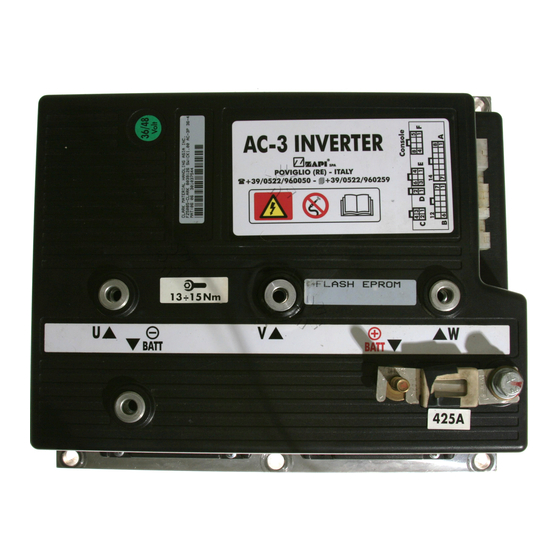
Zapi ZAPIMOS Series Installation And User Manual

Zapi ZAPIMOS Series Installation And User Manual

Hide thumbs Also See for ZAPIMOS Series:

Advertisement

LEGEND .............................................................................................................. 3
COLOUR CODES (Single Colours) ...................................................................... 3
1
Introduction to the ZAPI-MOS family .......................................................... 4
2
General characteristic ................................................................................... 5
2.1
Technical Specification.......................................................................... 5
2.2
Control Units.......................................................................................... 5
2.2.a Microswitches .............................................................................. 5
2.2.b Potentiometer ............................................................................... 6
2.3
Safety & Protection Features. ............................................................... 7
2.4
Direction Orientation ............................................................................. 7
2.5
Operational Features ............................................................................ 8
2.6
SEM2 chopper diagnosis ...................................................................... 9
2.7
Thermal Considerations. ....................................................................... 9
2.8
General Instructions and Precautions ................................................. 10
3
Installation. .................................................................................................. 11
3.1
Connection Cables. ............................................................................. 11
3.2
Contactors. .......................................................................................... 11
3.3
Fuses. ................................................................................................. 11
3.4
Description of SEM 2 Connectors. ...................................................... 12
3.5
Description of Power Connections ...................................................... 14
3.6
Mechanical Drawing & Dimensions ..................................................... 15
4
Programming & Adjustments using Digital Console ............................... 16
4.1
Adjustments via Console ..................................................................... 16
4.2
Description of Console & Connection .................................................. 16
4.3
Description of Standard Console Menu ............................................... 17
5
SEM2 Traction ............................................................................................. 18
5.1
Description of Programmable Functions (Options). ............................ 19
5.2
5.3
Table of Adjustments........................................................................... 22
5.4
SEM 2 Traction Standard Wiring Diagrams ........................................ 23
5.5
Sequence for SEM 2 Traction Settings. .............................................. 24
6
SEM 2 Diagnostics ...................................................................................... 26
6.1
Analysis of Alarms displayed on the Console ..................................... 27
6.2
Tester. Description of the Functions ................................................... 30
6.3
Description of the Console SAVE Function ......................................... 32
6.4
Description of Console RESTORE Function. ...................................... 33
6.5
Description of Alarms Menu. ............................................................... 34
6.6
Description of Console PROGRAM VACC function. ........................... 35
INDEX
Page
Page 1

Advertisement

Table of Contents
loading
Need help?

Need help?

Do you have a question about the ZAPIMOS Series and is the answer not in the manual?

Questions and answers

Subscribe to Our Youtube Channel

Summary of Contents for Zapi ZAPIMOS Series

  • Page 1: Table Of Contents

    INDEX Page LEGEND ......................3 COLOUR CODES (Single Colours) ..............3 Introduction to the ZAPI-MOS family ............4 General characteristic ................... 5 Technical Specification................5 Control Units..................5 2.2.a Microswitches ................5 2.2.b Potentiometer ................6 Safety & Protection Features..............7 Direction Orientation ................
  • Page 2 Recommended Spare parts for SEM 2 ............36 Periodic Maintenance to be repeated at times indicated......37 = The information contained in the paragraphs marked with this symbol is essential for the purpose of safety. SIGNED IN APPROVAL COMPANY DEPT. SERVICES MANAGEMENT EXECUTIVE ENGINEERING SECTION EXECUTIVE EXPORT MANAGER...
  • Page 3: Legend

    Speed Reduction 1 Microswitch Speed Reduction 2 Microswitch Main Contactor Voltage to Negative of Motor COLOUR CODES (SINGLE COLOURS) The following Codes represent the colours of individual wires used by Zapi (Unless specified otherwise). - Orange - White BB - Blue...
  • Page 4: Introduction To The Zapi-Mos Family

    1 INTRODUCTION TO THE ZAPI-MOS FAMILY The ZAPIMOS chopper family represents ZAPI’s answer to the needs of the 90’s. To ensure that products remain on the market, without running the risk of becoming technically obsolescent, the ZAPIMOS family offers the following features: - Advanced technology.
  • Page 5: General Characteristic

    2 GENERAL CHARACTERISTIC 2.1 TECHNICAL SPECIFICATION Chopper for Separately Excited DC motors ...........2.5 ÷ 5.5kW Regenerative Braking. Voltage Range ..................24 to 48 Volts DC Maximum Field Current (all the versions ............. 50 Amps Armature Switching Frequency ................16kHz Field Switching Frequency ..................1kHz Maximum Ambient temperature ................
  • Page 6: Potentiometer

    2.2.b Potentiometer The Potentiometer should be wired in the 3 - Wire Configuration. CPOT (A2) signal ranges from 0 to 10V. Minimum Potentiometer Resistance : 500W Maximum Potentiometer Resistance : 10kW Faults can occour if the potentiometer is out of this range. The Procedure for automatic potentiometer signal aquisition is carried out using the Console.
  • Page 7: Safety & Protection Features

    2.3 SAFETY & PROTECTION FEATURES. - Connection Errors : All Inputs are protected against connection errors. - Thermal Protection : If the chopper temperature exceeds 80°C, the maximum current reduces in proportion to the thermal increase. The temperature can never exceed 85°C. - Low Battery Charge : When the battery charge is low, the maximum current is reduced proportionally to the battery discharge.
  • Page 8: Operational Features

    2.5 OPERATIONAL FEATURES - Speed Control . - Optimum sensitivity at low speeds. - Speed Reductions in both the directions. Levels can be set using Console. - Regenerative Braking based on deceleration ramps. - Three different modes of Braking : Release Braking, Inversion Braking, Speed Limit Braking.
  • Page 9: Sem2 Chopper Diagnosis

    2.6 SEM2 CHOPPER DIAGNOSIS The microprocessor continually monitors the chopper and carries out diagnostic proce- dures on the main functions. The diagnosis is made in 4 points: 1) Diagnosis on key Switch closing that checks: the Watch Dog Circuits, the current sensor, VMN point, Contactor Drivers, the switch sequence for operation is correct, and the output of the accelerator or tiller is correct.
  • Page 10: General Instructions And Precautions

    If it is necessary to use two or more control units (eg. Lift + traction), the choppers must be of the High Frequency Zapi family. - Do not connect the chopper to a battery with a different nominal voltage to the value indicated on the chopper.
  • Page 11: Installation

    3 INSTALLATION. Install the chopper baseplate onto a flat metallic surface that is clean and unpainted. Apply a thin layer of thermo-conductive grease between the two surfaces to permit better heat dissipation. Despite the protection provided against external agents, the continuous attack of corro- sive elements and substances may cause oxidization of connector contacts, resulting in bad operation.
  • Page 12: Description Of Sem 2 Connectors

    3.4 DESCRIPTION OF SEM 2 CONNECTORS. PIN REFERENCE DESCRIPTION PLED Positive of Diagnostic Red Led. NLED Negative of Diagnostic Red Led. Output Current is 12mA, for this standard type Led. B+ Supply into logic Downstream of 10A Fuse & Key Switch. Positive Supply to Hand Brake and Brush / SR2 Microswitches.
  • Page 13 PIN REFERENCE DESCRIPTION Positive Common Feed to Rev, Fwd, SR1, PB, and Seat Microswitches. Input from Reverse Direction Microswitch. Active High. Input from Forward Direction Microswitch. Active High. Input from First Speed Reduction Switch. Active Low. Input from Pedal Brake Switch. Active High. SEAT Input from Seat Switch.
  • Page 14: Description Of Power Connections

    NOTES: 1) The BRUSH / SR2 and HB inputs could be connected to Battery Negative (B8). It is necessary to change the internal link “B” from 1-2 to 2-3. In this case the Normally Closed microswitches need to be Normally Open, and the Normally Open microswitches need to be Normally Closed.
  • Page 15: Mechanical Drawing & Dimensions

    3.6 MECHANICAL DRAWING & DIMENSIONS Page 15...
  • Page 16: Programming & Adjustments Using Digital Console

    4 PROGRAMMING & ADJUSTMENTS USING DIGITAL CONSOLE 4.1 ADJUSTMENTS VIA CONSOLE Adjustment of Parameters and changes to the chopper’s configuration are made using the Digital Console. The Console is connected to the “G” connector of the SEM 2 Chopper. Pay attention to the polarity of the Console Connector when connecting to the chopper.
  • Page 17: Description Of Standard Console Menu

    4.3 DESCRIPTION OF STANDARD CONSOLE MENU Page 17...
  • Page 18: Sem2 Traction

    5 SEM2 TRACTION - Input for 3 Wire Potentiometer. - 3 Speed Reductions. - Input for Tiller Switch or Seat Switch (delayed). - Input for Brake Pedal Microswitch. - Input for Motor Thermal Switch. - Management of Backing Speed (Programmable). Page 18...
  • Page 19: Description Of Programmable Functions (Options)

    5.1 DESCRIPTION OF PROGRAMMABLE FUNCTIONS (OPTIONS). Using the CONFIG MENU of the console, it is possible to select from the following options: SUBMENU “SET OPTIONS”: HOUR COUNTER: - RUNNING: The counter registers travel time only. - KEY ON: The counter registers when the key switch is Closed. BRUSH SWITCH: - PRESENT: The Brush Switch provides an input signal from the...
  • Page 20 Flow Chart showing how to make changes to Configuration Menu using Digital Con- sole. (Standard Eprom CK ULTRA fitted). 1) Opening Zapi Menu. 2) Press Top Left & Top Right Buttons simultaneously to enter the Config.Menu. 3) The Display will show : 4) Press ROLL UP (Top Left Button) until SET OPTIONS appears.
  • Page 21: Description Of Parameters That May Be Programmed

    5.2 DESCRIPTION OF PARAMETERS THAT MAY BE PROGRAMMED In addition to the Configuration, Parameter settings may be made by Zapi using stand- ard default settings, settings to Customer Specifications, or the customer may make changes according to the application, using a Digital Console.
  • Page 22: Table Of Adjustments

    15 CREEP SPEED = Minimum Speed. This Parameter sets the minimum voltage applied to the motor at the start of travel. 16 SEAT MICRO DELAY = Delay time after Seat Microswitch has opened. 17 HYDRO TIME = Operating time for Steering Contactor after controller has oper- ated.
  • Page 23 Flow Chart showing how to make Programme changes using Digital Console fitted with Eprom CK ULTRA. 1) Opening Zapi Display. 2) Press ENTER to go into the General Menu. 3) The Display will show : 4) Press ENTER to go into the Parameter Change facility.
  • Page 24: Sem 2 Traction Standard Wiring Diagrams

    5.4 SEM 2 TRACTION STANDARD WIRING DIAGRAMS Page 24...
  • Page 25: Sequence For Sem 2 Traction Settings

    5.5 SEQUENCE FOR SEM 2 TRACTION SETTINGS. When the Key Switch is Closed, if no Alarms or Errors are present, the Console Display will be showing the Standard Zapi Opening Display. If the chopper is not Configured to your requirements, follow the Sequence detailed on Page 20.
  • Page 26: Sem 2 Diagnostics

    6 SEM 2 DIAGNOSTICS As described in the Chopper Diagnostics on Page 9, the following listing shows likely problems associated with the Flashing RED LED. N° FLASHES MESSAGE NOTES LOGIC FAILURE Problem with Logic, or General Contactor. MICRO ST6215 KO Problem with the Safety circuit of Microproc- essor.
  • Page 27: Analysis Of Alarms Displayed On The Console

    6.1 ANALYSIS OF ALARMS DISPLAYED ON THE CONSOLE LOGIC FAILURE #1 During the initial diagnosis the main Microprocessor performs a check of the Main Contactor's control circuit, and verifies the condition. If this is not correct this Alarm is generated. MICRO ST6215 KO During the initial diagnosis the main Microprocessor tests and verifies the operation of the safety microprocessor.
  • Page 28 VFIELD NOT OK This test is made at standby with the Main Contactor open. In this condition the voltage on both the connections of field must be to around 1/ 2 VBatt. This alarm is generated if the field voltage is different from this value. Possible causes: a) Frame fault on the motor to chassis.
  • Page 29 16 CONTACTOR CLOSED This check is made during the initial diagnosis. With the coil of the Main Contactor de-energised, the capacitors should not be charged, unless there is divert resistor across the power poles. Possible causes: a) The contactor power poles are welded b) This alarm could be generated if the Main Contactor has opened, but there is a problem with either the field circuit, or a problem detected by the safety micro- processor.
  • Page 30: Tester. Description Of The Functions

    nominal value. 6.2 TESTER. DESCRIPTION OF THE FUNCTIONS The most important input or output signals can be measured in real time using the TESTER function of the console. The Console acts as a multimeter able to read volt- age, current and temperature. The following definition listing shows the relative meas- urements : 1) BATTERY VOLTAGE: level of battery voltage measured at the input to the key switch.
  • Page 31 OFF/ GND = temperature of the motor within the limits. Sensor is not operating. Flow Chart showing how to use the TESTER function of the Digital Console. 1) Opening Zapi Display. 2) Press ENTER to go into the General menu.
  • Page 32: Description Of The Console Save Function

    9) Press ENTER to commence SAVE routine. 10) You can see the items that are being stored whilst the SAVE routine is happening. 11) When finished, the Console shows : 13) Press OUT to return to the Opening Zapi Display. Page 32...
  • Page 33: Description Of Console Restore Function

    11) You can see the items that are being stored in the chopper memory whilst the RESTORE routine is happening. 12) When finished the Console displays : 13) Press OUT to return to the Opening Zapi Display . Page 33...
  • Page 34: Description Of Alarms Menu

    10) When you have finished looking at the Alarms, press OUT to exit the ALARMS menu. 11) The Display will ask CLEAR LOGBOOK ? 12) Press ENTER for yes, or OUT for NO. 13) Press OUT to return to the Opening Zapi Display. Page 34...
  • Page 35: Description Of Console Program Vacc Function

    11) Select the Reverse Direction and repeat Item 10. 12) When finished , press OUT. 13) The Display will ask : ARE YOU SURE ?. 14) Press ENTER for yes, or OUT for NO. 15) Press OUT again to return to the Opening Zapi Menu. Page 35...
  • Page 36 7 RECOMMENDED SPARE PARTS FOR SEM 2 Part Number Description C16504 Protected 300A Air Fuse. C16503 Protected 200A Air Fuse C16520 6.3A 20mm Control Circuit Fuse P99060 Red LED C12373 9 Way Molex Connector C12372 8 Way Molex Connector C12371 3 Way Molex Connector C12370 2 Way Molex Connector...
  • Page 37 During periodic checks, if a technician finds any situation that could cause damage or compromise safety, the matter should be bought to the attention of a Zapi Agent imme- diately. The Agent will then take the decision regarding operational safety of the ma- chine.
  • Page 38 INSTALLATION AND USER MANUAL CHOPPER SEM2...

This manual is also suitable for:

Sem2

Table of Contents