Table of Contents
Advertisement
Quick Links
Advertisement
Table of Contents

Subscribe to Our Youtube Channel
Related Manuals for Stealth SAQ-1318


Summary of Contents for Stealth SAQ-1318
- Page 1 Product Model # SAQ-1318 Item # 3300382 3 Gallon Quieter Air Compressor OPERATOR’S MANUAL CAUTION: To Reduce The Risk Of Injury, User Must Read And Understand Operator’s Manual. Save These Instructions For Future Reference. 1-888-899-0146 Toll Free Helpline:...
-
Page 2: Table Of Contents
TABLE OF CONTENTS Technical Specifications......................Safety Guidelines........................3 Key Parts Diagram........................5 Assembly Instructions......................7 Operating Instructions......................8 Maintenance..........................10 Troubleshooting........................11 Exploded View.......................... 13 Parts List............................ 14 Warranty............................ 15 TECHNICAL SPECIFICATIONS PRODUCT NUMBER 3300382 RUNNING HORSEPOWER TANK SIZE(TOTAL) 3U.S. Gallons(11L) AIR DELIVERY(CFM*)@40PSI AIR DELIVERY(CFM*)@90PSI CUT-IN PRESSURE(PSI) -
Page 3: Safety Guidelines
SAFETY GUIDELINES Important Safety Information The manufacturer cannot possibly anticipate every possible circumstance that might involve a hazard. The warnings in this manual, and the tags and decals affixed to the unit are, therefore, not all-inclusive. If you use a procedure, work method, or operating technique that the manufacturer does not specifically recommend, you must satisfy yourself that it is safe for you and others. - Page 4 SAFETY INFORMATION DO NOT OPERATE THIS UNIT UNTIL YOU READ AND UNDERSTAND THIS INSTRUCTION MANUAL FOR SAFETY, OPERATION, AND MAINTENANCE INSTRUCTIONS. WARNING Risk of fire caused by sparks from motor and pressure switch could result in death or serious injury. Do not operate compressor near flammable gas or vapor.
-
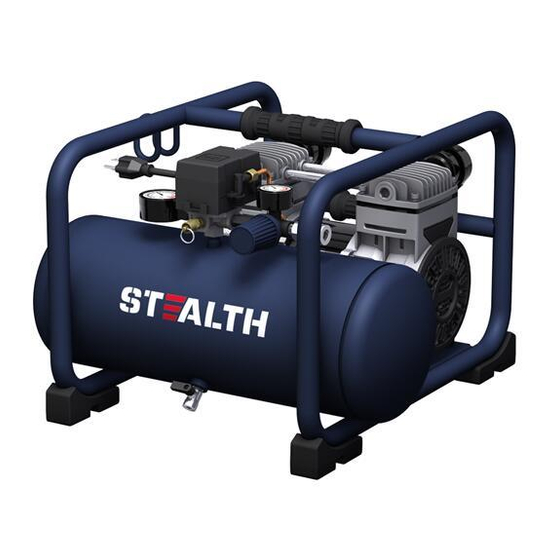
Page 5: Key Parts Diagram
KEY PARTS DIAGRAM Electrical Motor Outlet Pressure Gauge Air Compressor Pump Quick Coupler Safety Valve Drain Valve ON/OFF Switch Air Tank Air Pressure Regulator Power Cord Tank Pressure Gauge... - Page 6 PARTS DESCRIPTION Electric Motor The motor is used to power the pump. It is equipped with a thermal overload protector. If the motor overheats for any reason, the thermal overload protector will shut it down in order to prevent the motor from being damaged.
-
Page 7: Assembly Instructions
ASSEMBLY INSTRUCTIONS Unpack the air compressor unit. Inspect the unit for damaged. If the unit has been damaged, contact the • retailer immediately. Check the air compressor’s identification label to ensure that you have purchased the intended model and • that it has the required pressure rating for its intended use. -
Page 8: Operating Instructions
OPERATING INSTRUCTIONS Break in the pump 1.Set the ON/OFF switch (1) to the OFF position (Fig C). Fig C 2.Open tank drain valve (1) by turning it counter-clockwise to permit the air to escape and prevent air pressure build-up in the air tank during the break-in period (Fig D). Fig D 3.Turn the air pressure regulator knob (1) clockwise until it stops (Fig E). - Page 9 OPERATING INSTRUCTIONS Before each start-up Fig H 1.Set the ON/OFF switch (1) to the OFF position (Fig H). 2.Turn the air pressure regulator knob (1) counter-clockwise until it stops (Fig I). Fig I 3.Attach hose and accessories (Fig J).(Hose and accessories need to be purchased Fig J separately.) How to start...
-
Page 10: Maintenance
MAINTENANCE SERVICE ITEM DESCRIPTION / REASON INTERVAL Through normal operation of your air compressor, condensation of water will accumulate in the tank. To prevent corrosion of the tank from the inside, condensation must be drained at the end of every workday. Be sure to wear protective goggles. -
Page 11: Troubleshooting
TROUBLESHOOTING SOLUTIONS PROBLEM POSSIBLE CAUSE The power cord is not plugged in. Plug the power cord into a grounded outlet. The on/off switch is in the O (OFF) Set the on/off switch to the ON position. position. The extension cord is the wrong wire Check extension cord information for the proper gauge or is too long. - Page 12 TROUBLESHOOTING SOLUTIONS PROBLEM POSSIBLE CAUSE Check the fittings with soapy water. Tighten or There is a leak at one of the fittings. reseal leaking fittings (apply plumber s tape on threads).Do not over tighten. Close the drain valve. The tank drain valve is open. Clean or replace the air filter element.
-
Page 13: Exploded View
EXPLODED VIEW... -
Page 14: Parts List
PARTS LIST Description Qty. Description Qty. Check Valve Screw M8 Control Panel Motor Pump Assembly Pressure Regulator Air Filter Pressure Regulator Knob Handgrip Pressure Gauge Latch Assembly Rubber Hose Handle Screw M4x10 Flange Nut M5 Head Screw M5x12 Screw M8x40 Quick Coupler Pressure Switch Transfer Tube... -
Page 15: Warranty
STEALTH WARRANTY LIMITED LIFETIME WARRANTY ONLY THE PUMP AND MOTOR ARE COVERED IN THE LIFETIME WARRANTY Warranty covers any defects in materials or workmanship of the enclosed product. Alton Industry Ltd. Group will repair or replace any defective materials due to craftsmanship of the product.
Need help?
Do you have a question about the SAQ-1318 and is the answer not in the manual?
Questions and answers