Table of Contents
Advertisement
Quick Links
Document Number:
XE-FDA3PM-R0A
THREE PHASE GENERATOR DISPLAY
FREQUENCY READOUT OF GENERATOR
TEL ( 631 ) 724-8888 FAX ( 631 ) 360-9727 TOLL FREE 1-800-645-0074
FROG-D 3P
MODEL FDA300
FOR DELTA WINDINGS
FOR STAR WINDINGS
FIRE RESEARCH CORPORATION
www.fi reresearch.com
26 Southern Blvd., Nesconset, NY11767
1
FDA300 Rev0306
Advertisement
Table of Contents

Subscribe to Our Youtube Channel
Related Manuals for FRC FROG-D 3P


Summary of Contents for FRC FROG-D 3P
- Page 1 FDA300 Rev0306 Document Number: XE-FDA3PM-R0A FROG-D 3P THREE PHASE GENERATOR DISPLAY FREQUENCY READOUT OF GENERATOR MODEL FDA300 FOR DELTA WINDINGS FOR STAR WINDINGS FIRE RESEARCH CORPORATION www.fi reresearch.com 26 Southern Blvd., Nesconset, NY11767 TEL ( 631 ) 724-8888 FAX ( 631 ) 360-9727 TOLL FREE 1-800-645-0074...
-
Page 2: Table Of Contents
FDA300 Rev0306 CONTENTS Table of Contents CONTENTS ........................ 2 INTRODUCTION ...................... 3 Overview ........................ 3 Features ........................3 Specifications ......................3 GENERAL DESCRIPTION ..................4 Components ......................4 Controls and Indicators ..................5 INSTALLATION ......................6 Install Display Module ..................6 Install Current Sensor .................... -
Page 3: Introduction
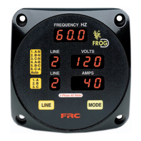
FDA300 Rev0306 INTRODUCTION Overview The Fire Research FROG-D is a three phase generator output display panel for 50/60 Hz generators rated from 10 to 135 kW with delta or star windings. The ultra-brite LED displays on the FROG-D will show the operator generator frequency, current on each lines, and AC line voltage (phase to neutral or phase to phase. -
Page 4: General Description
Display Module The display module is waterproof and can be mounted anywhere on the electrical panel. The FROG-D 3P display module has a square flange with overall dimensions of 4.25" X 4.25". A cutout hole of 3.75" in diameter is required. -
Page 5: Controls And Indicators
FDA300 Rev0306 Controls and Indicators All controls and indicators are located on the front of the display module. FREQUENCY HZ Display Shows generator frequency in hertz. LINE Displays Shows the selected line to view voltage or current. See Operation Section for complete description. -
Page 6: Installation
FDA300 Rev0306 INSTALLATION The FROG-D 3P must match the rated output of the generator. It is factory set from 10 to 135 kW in 5 kW increments. Ensure that the generator power rating and the FROG-D rating match. Install Display Module 1. -
Page 7: Figure 2. Display Module Mounting Dimensions
FDA300 Rev0306 Panel Cutout A 3.75" hole is recommanded. 3.5" 4.25" 3.72" 3.5" 4.25" Mounting holes are clearance or tapped for 10-32 screws. 2.38" .75" Figure 2. Display Module Mounting Dimensions... -
Page 8: Install Current Sensor
FDA300 Rev0306 Install Current Sensor Three current sensors are supplied. It is best to mount the sensors in the circuit breaker box. For each line that is to be monitored, run the wire from the generator through the current sensor to the input side of the circuit breaker. (Refer to Wiring section.) Current Sensor Ratio:... -
Page 9: Install Voltage Transformer
Install the buzzer close to the control module so the audible warning is easily associated with the visual warning on the display. The optional buzzer provided by FRC requires a cutout hole of 1-1/8” (1.125”). (Refer to Wiring section.) Note: Refer to Wiring section, Star or Delta Windings for generator connections. -
Page 10: Operation
During normal operations the mode button is used to display the accumulated hours and hydraulic oil temperature if this option is installed. The first time the MODE button is pressed, the FROG-D 3P will display the generator hours. Generator Operating Time is:... -
Page 11: Table 1. Line Displays
FDA300 Rev0306 LINE Displays and Button On power up the LINE displays will be set to Auto. In Auto mode, the displays will scroll continuously through all six selectable options and show the corresponding voltages and currents in the display windows. To read the voltage and current for a specific line press and hold the LINE button until the number corresponding to the desired selection shows in the LINE window. -
Page 12: Wiring
FDA300 Rev0306 WIRING The following figures include the schematics, wiring diagrams, block diagrams, and cables for the FROG-D 3P. Connector Key A 6-Pin Deutsch B 2-Pin Deutsch Power Supply Options Current Sensors Black Plug Transformers Options Cable Connector Gray Pin/Wire... - Page 13 FDA300 Rev0306 Current Sensors Current Sensor Cable (See Sheet 1) Black Wire Red Wire Black Wire White Wire Black Wire Line 1 White Wire Green Wire White Wire Black Wire Line 2 Blue Wire Brown Wire White Wire Line 3 Note: Refer to Star or Delta windings diagrams for generator connections.
-
Page 14: Star Winding Connections
FDA300 Rev0306 Star Winding Connections From Generator N C B A 6-Pin Deutsch Receptacle to Transformer Cable 6-Pin Deutsch Receptacle Transformers to Current Sensor Cable Current Refer to Figure 5 for pin Sensors number and wire color. 240v Star Circuit Figure 6. -
Page 15: Delta Winding Connections
FDA300 Rev0306 From Generator N C B A Transformers Current Sensors 240v Delta Circuit Figure 7. Delta Winding Connections...
Need help?
Do you have a question about the FROG-D 3P and is the answer not in the manual?
Questions and answers