
Subscribe to Our Youtube Channel
Related Manuals for SMC Sierra Monitor 3600-I

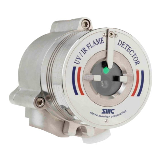
Summary of Contents for SMC Sierra Monitor 3600-I
- Page 1 Model 3600-I Triple IR (IR3) Flame Detector APPLICABILITY & EFFECTIVITY Effective for flame detectors manufactured after September 2016. Manual # T15014 Document Revision: A1...
- Page 2 Model 3600-I IR3 Flame Detector ©2016 Sierra Monitor. All rights reserved. Manual Number: T15014 This manual contains intellectual property that was developed by Sierra Monitor Corporation Inc. and is protected by the copyright laws of the United States, international copyright treaties, and all other applicable national laws.
-
Page 3: About This Guide
Model 3600-I IR3 Flame Detector ABOUT THIS GUIDE This guide describes the Model 3600-I Triple IR (IR3) Flame Detector along with their features. Additionally, the guide provides instructions on how to install, operate and maintain the detector. This guide includes the following Sections and appendixes: ... -
Page 4: Abbreviations And Acronyms
Model 3600-I IR3 Flame Detector ABBREVIATIONS AND ACRONYMS Abbreviation Meaning ATEX Atmosphere Explosives American Wire Gauge Built In Test Electromagnetic Compatibility End of Line Field of View HART Highway Addressable Remote Transducer-communication protocol Immune at Any Distance IECEx International Electrotechnical Commission Explosion... -
Page 5: Table Of Contents
Model 3600-I IR3 Flame Detector TABLE OF CONTENTS About this Guide ............................3 Abbreviations and Acronyms ........................4 Introduction ............................9 Overview ............................9 Model and Types .......................... 10 Features and Benefits........................12 Principles of Operation ......................... 12 1.4.1 Hydrocarbon Fire Detection ....................13 1.4.2... - Page 6 Model 3600-I IR3 Flame Detector Operating the Detector ........................37 Powering Up ..........................37 Safety Precautions........................37 3.2.1 Default Functions Settings ....................38 Testing Procedures........................38 3.3.1 Automatic BIT Test ........................ 38 3.3.2 Manual BIT Test ........................39 3.3.3 Testing with Fire Simulator Model FS-1100 ................39 Maintenance and Troubleshooting ....................
- Page 7 Figure 44: RS-485 Networking ........................53 Figure 45: UV/IR Long Range Fire Simulator FS-1200 ................54 Figure 46: 3600-I IR3 Flame Detector Target Point ..................55 Figure 47: Detection Ranges ........................56 Figure 48: Flame Simulator – Side View ..................... 57 Figure 49: Flame Simulator –...
- Page 8 Model 3600-I IR3 Flame Detector Figure 57: Tilt Mount ........................... 61 Figure 58: Weather Protector Installed (Back View) ................... 62 Figure 59: Weather Protector Installed (Front View) .................. 62 Figure 60: Laser Detection Coverage Pointer..................... 63 Figure 61: Air Shield ............................ 63...
-
Page 9: Introduction
Model 3600-I IR3 Flame Detector INTRODUCTION Overview The Model 3600I is a flame detector that utilizes improved IR3 technology to provide state-of-the-art fire protection. The 3600I uses patented digital signal processing to analyze the spectral and dynamic characteristics of the measured infrared radiation to identify fire events with exceptional sensitivity and extreme immunity to false alarms. -
Page 10: Model And Types
Model 3600-I IR3 Flame Detector Model and Types The 3600-I Flame Detector is provided in various configurations depending on: Wiring options Temperature ranges Type of cable entries Housing type Required approval The configuration detail is included in the product part number on the product label and takes the form: 3600X-XXXXXX, where XXXXXX defines the model according to the above requirements. -
Page 11: Figure 3: Wiring Options
Model 3600-I IR3 Flame Detector The table below describes the wiring options in detail. Wiring Connections Provided Option Manual Fault Relay Alarm Relay 0-20mA Power RS-485 N.C. N.O. Sink Manual Fault Relay Alarm Relay 0-20mA Power RS-485 HART N.C. N.O, N.C. -
Page 12: Features And Benefits
EExde: Integral junction box for easy wiring SIL-2: TÜV approved Hazardous Area Certification: ATEX, IECEx and FM Principles of Operation This section describes the 3600-I principles of operation, which includes: Hydrocarbon Fire Detection, Section 1.4.1 Heated Optics, Section 1.4.2... -
Page 13: Hydrocarbon Fire Detection
Model 3600-I IR3 Flame Detector 1.4.1 Hydrocarbon Fire Detection A Model 3600-I IR3 Flame Detector is designed to detect flames in which carbon dioxide (CO ) is produced in the combustion process. These include all hydrocarbon flames, as well as other types of flames and burning materials such as wood or alcohol. -
Page 14: Hart Protocol
Model 3600-I IR3 Flame Detector 1.4.3 HART Protocol The 3600 Flame Detectors use the HART Protocol. HART Communication is a bi-directional industrial field communication protocol used to communicate between intelligent field instruments and host systems. HART is the global standard for smart process instrumentation and the majority of smart field devices installed in plants worldwide are HART-enabled. -
Page 15: Performance Considerations
Model 3600-I IR3 Flame Detector Performance Considerations This section describes performance aspects and includes: Detection Sensitivity, Section 1.5.1 Cone of Vision, Section 1.5.2 False Alarm Prevention, Section 1.5.3 Visual Indicators, Seciton 1.5.4 Output Signals, Section 1.5.5... -
Page 16: Other Fuels
Model 3600-I IR3 Flame Detector 1.5.1.3 Other Fuels The detector reacts to other types of fire as follows: The baseline fire refers to n-heptane 1ft (0.1m ) pan fire and is defined as 100% sensitivity For fuel fires – standard pan fire size: 1 ft (0.1 m... -
Page 17: Cone Of Vision
Model 3600-I IR3 Flame Detector 1.5.2 Cone of Vision Horizontal: 100° Figure 5: Horizontal Field of View Vertical: +50° (down) , -45° (up) Figure 6: Vertical Field of View Page 17 of 66... -
Page 18: False Alarms Prevention
Model 3600-I IR3 Flame Detector 1.5.3 False Alarms Prevention To prevent false alarms, the detector will not alarm or react to the radiation sources specified below. Immunity Distance in Radiation Source ** feet (meters)* Indirect or reflected sunlight Vehicle headlights (low beam) conforming to MS53023-1... -
Page 19: Visual Indicators
Model 3600-I IR3 Flame Detector 1.5.4 Visual Indicators One 3-color LED indicator is located inside the detector window, as shown in Figure 10. The detector statuses are listed in the LED Indications table below: Detector Status LED color LED mode... -
Page 20: Output Signals
Model 3600-I IR3 Flame Detector 1.5.5 Output Signals Outputs are available according to the default configuration or the wiring options selected for the detector. Determine the outputs model according to the table below. The detector incorporates several types of output suitable to different control systems: ... -
Page 21: Detector Status
Model 3600-I IR3 Flame Detector 1.5.6 Detector Status The possible detector function statuses are listed in the detector status table below. A more detailed fault analysis can be seen via HART or RS-485. Status Description Normal Normal operation. Built-In-Test being performed. -
Page 22: Optional Latching
Model 3600-I IR3 Flame Detector 1.5.6.1 Optional Latching Alarms are set as non-latching by default. However, the detector includes a latched alarm output capability, which operates according to the programmed function. If selected, upon detection of a fire, the detection signal is latched until a manual reset is performed (disconnecting the power supply or performing a manual BIT (see Section 1.6.2.3). -
Page 23: Internal Detector Tests
Model 3600-I IR3 Flame Detector Internal Detector Tests The detector performs two types of self-tests: Continuous Feature Test, Section 1.6.1 Built-In-Test (BIT), Section 1.6.2 1.6.1 Continuous Feature Test During normal operation, the detector tests itself continuously and indicates a fault if a failure is found. -
Page 24: Built-In-Test (Bit)
Model 3600-I IR3 Flame Detector 1.6.2 Built-In-Test (BIT) The detector’s Built-In-Test (BIT) also checks the following: Electronics circuitry Sensors Window cleanliness The detector can be set to perform the BIT in the following modes: Automatically and manually ... -
Page 25: Manual Bit
Model 3600-I IR3 Flame Detector 1.6.2.3 Manual BIT The BIT is manually initiated by momentarily connecting Terminal 3 with Terminal 2 (or a switch across these terminals in the safe area). If the BIT is unsuccessful, all outputs will function as described for Automatic BIT, but the BIT is now automatically executed every 1 minute. -
Page 26: Installing The Detector
Model 3600-I IR3 Flame Detector INSTALLING THE DETECTOR This Section provides basic guidelines for installing the detector. It does not attempt to cover all of the standard practices and codes of installation. Rather, it emphasizes specific points of consideration and provides some general rules for qualified personnel. -
Page 27: Unpacking The Product
Model 3600-I IR3 Flame Detector Unpacking the Product Upon receipt of the detector, check and record the following: 1. Verify the appropriate Purchase Order. Record the Part Number (P/N) and Serial Number of the detectors, and the installation date in an appropriate Log-book. -
Page 28: Installation Cables
Model 3600-I IR3 Flame Detector Repair of this equipment shall be carried out by suitably trained personnel in accordance with the applicable code of practice such as EN 60079-19 The certification of this equipment relies upon the following materials used in its construction: Enclosure –... -
Page 29: Installing The Tilt Mount (Part No. 3600-001)
Model 3600-I IR3 Flame Detector Installing the Tilt Mount (part no. 3600-001) The Tilt Mount enables the detector to be rotated up to 60º in all directions. The picture below shows the Detector mounted on the Tilt Mount. Figure 19: Detector with Tilt Mount 2.6.1 Tilt Mount Specifications... -
Page 30: Tilt Mount Assembly
Model 3600-I IR3 Flame Detector 2.6.2 Tilt Mount Assembly Figure 22 shows the Tilt Mount Assembly. Figure 22: Tilt Mount Assembly Figure 23 shows the Tilt Mount Assembly with dimension in both millimeters and inches. Figure 23: Tilt Mount Assembly (dimension in mm and inches) - Page 31 Model 3600-I IR3 Flame Detector ➣ To install the Tilt Mount and Detector: 1. Place the tilt mount in its designated location and secure it with four (4) fasteners through four (4) holes 7 mm in diameter. Use the 4 screws and spring washers according to the Kit –...
-
Page 32: Connecting The Detector
Model 3600-I IR3 Flame Detector Connecting the Detector This section describes how to connect the electric cabling to the detector. ➣ To connect the detector to the electrical cables 1. Disconnect the power. 2. Remove the back cover of the detector by removing four (4) socket head-screws in the cover bolts. -
Page 33: Verifying The Detector Wiring
RS-485-(1) RS-485 GND RS-485 GND RS-485 GND RS-485 GND RS-485 GND Figure 25: Model 3600-I IR3 Wiring Options *Available with the HART protocol. Keep the following in mind: RS-485 is used for communication network as specified in Appendix C... -
Page 34: Configuring The Detector
Model 3600-I IR3 Flame Detector Configuring the Detector The function setup can be reprogrammed using the RS-485 connection or using the HART Protocol as follows: Sierra Monitor Host Software – The Sierra Monitor Host Software is for use on a PC or laptop. -
Page 35: Sensitivity
Model 3600-I IR3 Flame Detector 2.8.1 Sensitivity The detector offers four sensitivity settings. The settings refer to an n-heptane or gasoline fire of 1ft (0.1m ), from low sensitivity of 50 ft (15m) to 215 ft (65m). Detector Distance in feet... -
Page 36: Function Set-Up
Model 3600-I IR3 Flame Detector 2.8.4 Function Set-up Select the desired functions as detailed below. Function Setting Yes: Enable Alarm latching. Alarm Latch No: Disable Alarm latching (default). Yes: Activate Auxiliary Relay at Warning level. Auxiliary Relay** No: Activate Auxiliary Relay at Alarm level (default). -
Page 37: Operating The Detector
Model 3600-I IR3 Flame Detector OPERATING THE DETECTOR This Section describes how to power up and test the detector. It also includes some very important safety checks that to perform before operating the detector. Powering Up This section describes how to power up the detector. Follow the instructions below to obtain optimal performance from the detector over its life cycle. -
Page 38: Default Functions Settings
Model 3600-I IR3 Flame Detector 3.2.1 Default Functions Settings The table below lists the default function configuration supplied with the detector: Function Value Notes Sensitivity 100/30 Alarm Delay Alarm Latch In wiring options 1, 2, 3 the Auxiliary Relay is not Auxiliary Relay available. -
Page 39: Manual Bit Test
Model 3600-I IR3 Flame Detector 3.3.2 Manual BIT Test Important: If the function setup Alarm BIT and/or Auxiliary BIT are set to Yes (default No), the Alarm, Auxiliary Relay and 0-20mA outputs are activated during a Manual BIT. Therefore, automatic extinguishing systems or any external devices that may be activated during BIT must be disconnected. -
Page 40: Maintenance And Troubleshooting
Model 3600-I IR3 Flame Detector MAINTENANCE AND TROUBLESHOOTING This Section deals with preventive maintenance, describes possible faults in detector operation and indicates corrective measures. Ignoring these instructions may cause problems with the detector and may invalidate the warranty. When a unit requires service, contact Sierra Monitor or its authorized distributor for assistance. -
Page 41: Keeping Maintenance Records
Model 3600-I IR3 Flame Detector 4.1.3 Keeping Maintenance Records It is recommended that maintenance operations performed on a detector are recorded in a Log-book. The record should include the following: Installation date, and contractor Serial and tag no ... - Page 42 Model 3600-I IR3 Flame Detector APPENDIX Page 42 of 66...
-
Page 43: Appendix A. Specifications
Model 3600-I IR3 Flame Detector APPENDIX A. SPECIFICATIONS Appendix A.1. Technical Specifications Spectral Response Three IR Bands Detection Range Fuel ft / m Fuel ft / m [at highest Sensitivity Setting n-Heptane 215 / 65 Kerosene 150 / 45 for 1ft (0.1m... -
Page 44: Appendix A.3. Outputs
Model 3600-I IR3 Flame Detector Appendix A.3. Outputs Electrical There are five output-wiring options. These options must be defined at Interface the factory per the customer order and cannot be changed at the customer facility. Appendix B.1 for the wiring/terminal diagram for each wiring option. - Page 45 Model 3600-I IR3 Flame Detector HART Protocol The HART is a digital communication signal at a low level on top of the 0-20mA. This is a bi-directional field communication protocol used to communicate between intelligent field instruments and the host system.
-
Page 46: Appendix A.4. Mechanical Specifications
Model 3600-I IR3 Flame Detector Appendix A.4. Mechanical Specifications Enclosure Options Stainless Steel 316 Aluminum, heavy duty copper free (less than-1%), red epoxy enamel finish FM, CSA Hazardous Area Approvals Class I Div. 1 Groups B, C and D;... -
Page 47: Appendix A.7. Environmental Specifications
Model 3600-I IR3 Flame Detector Appendix A.7. Environmental Specifications The 3600-L is designed to withstand harsh environmental conditions. Designed to meet MIL-STD-810C, method 501.1 procedure II High Temperature Operating temperature: +167°F (+75°C) Storage temperature: +185°F (+85°C) ... -
Page 48: Appendix B. Wiring Instructions
Model 3600-I IR3 Flame Detector APPENDIX B. WIRING INSTRUCTIONS Appendix B.1. General Instructions for Electrical Wiring Follow the instructions detailed in this section for determining the correct wire gauge to be used for the installation. 1. Use the table below to determine the required wire gauge/size for general wiring, such as relay wiring. -
Page 49: Appendix B.2. Typical Wiring Configurations
Model 3600-I IR3 Flame Detector Appendix B.2. Typical Wiring Configurations This section describes examples of typical wiring configurations. Figure 37: Wiring Terminals Terminals Wiring Detector Model Option Fault Relay 3600I: 1XXXX 0-20mA (Sink) 0-20mA (Sink) N.C. Fault Relay Alarm Relay... -
Page 50: Figure 39: Typical Wiring For 4 Wire Controllers (Using Option 1 Or 2 Wiring)
Model 3600-I IR3 Flame Detector Figure 39: Typical Wiring for 4 Wire Controllers (Using Option 1 or 2 Wiring) Figure 40: 0-20mA Wiring Option 1 (Sink 4-Wire) – Default Page 50 of 66... -
Page 51: Figure 41: 0-2Ma Wiring Option 1 (Converted To Source 3-Wire)
Model 3600-I IR3 Flame Detector Figure 41: 0-2mA Wiring Option 1 (Converted to Source 3-Wire) Figure 42: 0-20mA Wiring Option 1 (Unisolated Sink 3-Wire) Page 51 of 66... -
Page 52: Figure 43: 0-2Ma Wiring Option 2 & 3 (Source 3-Wire Available With Hart Protocol)
Model 3600-I IR3 Flame Detector Figure 43: 0-2mA Wiring Option 2 & 3 (Source 3-Wire Available with HART Protocol) NOTE: There are no 0-20mA outputs in wiring options 4 and 5. Page 52 of 66... -
Page 53: Appendix C. Rs-485 Communication Network
Model 3600-I IR3 Flame Detector APPENDIX C. RS-485 COMMUNICATION NETWORK Appendix C.1. RS-485 Overview By using the RS-485 network capability of the UV/IR detector and additional software, it is possible to connect up to 32 detectors in an addressable system with four (4) wires only (2 for power and 2 for communication). -
Page 54: Appendix D. Accessories
Model 3600-I IR3 Flame Detector APPENDIX D. ACCESSORIES This appendix describes the accessories that can help maximize fire detection with the IR3 flame detector: Appendix D.1. Long Range IR3 Fire Simulator The IR3 Long Range Fire Simulator FS-1100 is designed specifically for use with IR3 flame detectors. The Fire Simulator emits IR radiation in a unique sequential pattern corresponding to and recognizable by the IR3 detector as fire. -
Page 55: Appendix D.1.2. Operating Instructions
D.1.3), and the detector sensitivity. Target Point Figure 46: 3600-I IR3 Flame Detector Target Point 3. Aim the detector using the mechanical sight at the center of the detector. Activate the button and adjust the spot to the center of the detector. -
Page 56: Appendix D.1.3. Range
Model 3600-I IR3 Flame Detector Appendix D.1.3. Range Detector Detector Model Testing Distance Sensitivity Setting 50ft (15m) 6.6ft (2m) 100ft (30m) 19.6ft (6m) 3600-I 150ft (45m) 29.5ft (9m) 200ft (60m) 39.3ft (12m) Figure 47: Detection Ranges NOTE: The minimum distance from the detector is 30 in (75 cm). -
Page 57: Figure 48: Flame Simulator - Side View
Model 3600-I IR3 Flame Detector ➣ To replace the battery: 1. Place the Flame Simulator on a table in a safe area, not exceeding 40°C. 2. Release the locking screw (item 8, Figure 48). 3. Unscrew the battery back cover (item 3, Figure 48 &... -
Page 58: Figure 49: Flame Simulator - Rear View
Model 3600-I IR3 Flame Detector Figure 49: Flame Simulator – Rear View Figure 50: Flame Simulator – Front View Electronic Chamber Handle Sight Battery Chamber Reflector Back Cover Locking Screw Battery Back Cover Push Button Laser Diode Figure 51: Flame Simulator – General Part Identification... -
Page 59: Appendix D.1.5. Maintenance
Model 3600-I IR3 Flame Detector Figure 52: Flame Simulator – Battery Replacement Simulator Battery Pack Back Cover Locking Disc Figure 53: Flame Simulator – Battery Part Identification Appendix D.1.5. Maintenance 1. Ensure the Flame Simulator is charged before operation. 2. Ensure the reflector and window are clean. -
Page 60: Appendix D.1.6. Troubleshooting
Model 3600-I IR3 Flame Detector Appendix D.1.6. Troubleshooting Problem Solutions Laser flashes 3 Recharge the battery times Laser flashes 5 Operate the Flame Simulator again times Send the Flame Simulator for repair Laser does not turn Recharge the battery ... -
Page 61: Appendix D.1.8. Emi Compatibility
Model 3600-I IR3 Flame Detector Appendix D.1.8. EMI Compatibility Immunity Tests Title Basic Standard Level to be Tested Electrostatic discharge (ESD) IEC 61000-4-2 6 kV/8 kV contact/air 20 V/m (80 MHz to 1 GHz) Radiated Electromagnetic Field IEC 61000-4-3 10 V/m (1.4 GHz to 2 GHZ) 3 V/m (2.0 GHz to 2.7 GHz) -
Page 62: Appendix D.3. Weather Protection - P/N 777163
Model 3600-I IR3 Flame Detector Appendix D.3. Weather Protection – P/N 777163 The weather protector protects the detector from different weather conditions, such as snow and rain. Figure 58: Weather Protector Installed (Back View) Figure 59: Weather Protector Installed (Front View) -
Page 63: Appendix D.4. Laser Detection Coverage Pointer - P/N 777166
Model 3600-I IR3 Flame Detector Appendix D.4. Laser Detection Coverage Pointer – P/N 777166 The Laser Detection Coverage Pointer evaluates detector coverage on-site. The device is an add-on accessory that enables designers and installers to optimize detector location and assess the actual coverage of installed detectors. -
Page 64: Appendix E. Sil-2 Features
This appendix details the special conditions to comply with the requirements of EN 61508 for SIL 2. The 3600-I Flame Detector can only be used in low or high demand mode applications, see IEC 61508.4. Appendix E.1.1. Safety Relevant Parameters Do a functional check of the detector every 30 days. -
Page 65: Appendix E.1.2.3. Using The Alarm Relay Contact For Alerting
Model 3600-I IR3 Flame Detector Appendix E.1.2.3. Using the Alarm Relay Contact for Alerting 1. The following parameters shall be set: AUTOMATIC BIT Test = on Connected to N.C. contact of Alarm Relay Terminals Connected to Fault Relay Terminals 2. -
Page 66: Appendix F. Limited 2 Year Warranty
Model 3600-I IR3 Flame Detector APPENDIX F. LIMITED 2 YEAR WARRANTY Sierra Monitor Corporation (SMC) warrants its products to be free from defects in workmanship or material under normal use and service for two years after date of shipment. SMC will repair or replace without charge any equipment found to be defective during the warranty period.
Need help?
Do you have a question about the 3600-I and is the answer not in the manual?
Questions and answers