Table of Contents
Advertisement
Quick Links
Advertisement
Table of Contents

Summary of Contents for Adena RADA A-TC01
- Page 2 Precautions This manual details functions, installation, operation principles and methods of A-TC01 AI Tracking Camera. Please read this manual carefully before installation and use. 1. How to use In order to prevent this product or products connected to it from being damaged, please use it within its prescribed scope of use.
- Page 3 5. Install with caution Do not rotate the camera head violently, otherwise it may cause mechanical malfunction; This product should be placed on a stable desktop or other horizontal surfaces. Do not install the product obliquely, otherwise it may display inclined image; When installing the camera on top of TV or personal computer, use four double faced adhesive pads at the bottom for fixing;...
-
Page 4: Table Of Contents
Table of Contents System overview ........................4 1.1. System introduction ......................4 1.2. Product advantages ......................4 1.3. Product features ........................ 5 2. Port Introduction ........................... 6 3. Dimensions ............................. 8 4. Configuration tools........................9 4.1. Set IP address of the tracking camera ................9 4.2. -
Page 5: System Overview
1. System overview 1.1. System introduction A-TC01 AI Tracking Camera is a dual camera system that allows presenter tracking without any additional devices. Its dual system means that users can engage both cameras at the same time – wide angle shot from the lower camera, and presenter tracking shot from the upper PTZ camera. -
Page 6: Product Features
Super wide dynamic exposure: It solves the issue that a tracking object dims under strong light such as projector. Networked control interface: Control information of all products is transmitted via network, and it is suitable for product layout for all scenarios. 1.3. -
Page 7: Port Introduction
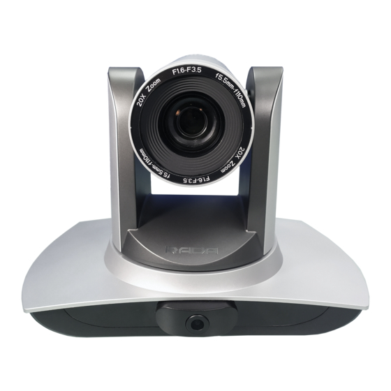
2. Port Introduction Front view Rear view 1. Close-up lens 2. Panorama lens 3. USB3.0 output 1 (panorama lens output) 4. HDMI output 1 (panorama lens output) 5. LAN network port for panorama lens 6. USB3.0 output 2 (close-up lens output) 7. - Page 8 Pin definition: Port Definition Data Terminal Ready Data Set Ready Transmit Data Signal ground Receive Data Signal ground IR OUT IR Commander Signal IR No Connection...
-
Page 9: Dimensions
3. Dimensions... -
Page 10: Configuration Tools
4. Configuration tools 4.1. Set IP address of the tracking camera Open IVESmart configuration tool, click “Settings” -> “IP address” -> “Search” (refer to Figure 5.1-1 for details), the configuration interface will display all valid devices in the LAN, check only “Teacher Tracking Camera” and click Confirm. Note: Computer with IVESmart tool should be in the same LAN with the camera to be configured. - Page 11 Figure 4.2.1 3. Set general view (panoramic) and presenter view (platform) preset positions. Please note that Panoramic Position preset is used when no targets are tracked. Platform Position preset is used when a target is tracked. Figure 4.2.2...
- Page 12 Draw zones for the presenter pickup (Platform Area), tracking (Teacher Track Area), and mask areas Platform area: this is the area where tracking targets are first acquired. Normally, this area is set up near the blackboard, on top of a platform, podium, or other place where your tracking targets will be standing in first.
-
Page 13: Other Tracking Parameters
Mask area: this area is used to cover items and places that may impact tracking performance, e.g. places with dynamic changes such as TVs, projector displays, doors, and windows. See Figure 4.2.5 below: Figure 4.2.5 4.3. Other Tracking Parameters Target lost: when the camera loses its target, it will return to the designated preset position. - Page 14 Track mode: Realtime track: camera will adjust image for the target’s minor • movements, e.g. hand waiving. Region track: camera will not adjust for minor movements, e.g. hand • waiving. Others set: Report location: this function is not used on A-TC01. •...
-
Page 15: Network Update
After adjusting settings, click “Save Param.” and, when ready “start” to begin tracking. 4.4. Network update A-TC01 can be updated via network and IVESmart tool. Click Configuration -> Network configuration & update to enter update interface, as shown below: Figure 4.4.1 When upgrading, please note that there are separate update options for the wide- angle camera (Panoramic) and tracking camera (Close-up camera). -
Page 16: Description Of Recording And Broadcasting Host
5. Description of recording and broadcasting host 5.1. Auto tracking control The recording and broadcasting host sends commands by LAN network port or concentrator RS232 serial port and controls automatic tracking motion of the tracking camera. When tracking mode is active, camera’s PTZ cannot be manually controlled;... -
Page 17: Action Code Docking
5.2. Action code docking Tracking status of teacher tracking camera will be fed back to the recording and broadcasting host via network (UDP transmission mode) or concentrator (RS232 serial port) in the form of action code. 1. Configure recording and broadcasting host address: If recording and broadcasting host uses LAN to receive action codes, then it needs to configure host address by IVESmart configuration tool. -
Page 18: Description Of The Remote Controller
6. Description of the remote controller 6.1. Description of keys 1. Standby key Long press standby key for 3s, camera enters standby mode, long press this key again for 3s, camera will perform self- inspection again and return to HOME position. When setting #0 as preset, when there is no action within 12s, the holder will return to #0 preset. -
Page 19: Set Menu
11. Set infrared remote control address of a camera [*] + [#] + [F1] : # 1 address [*] + [#] + [F2] : # 2 address [*] + [#] + [F3] : #3 address [*] + [#] + [F4] : #4 address 12. -
Page 20: System Parameter Settings
Language settings / Language: Select Settings: Enter submenu system parameter settings menu language, Chinese/English Camera parameters: Enter submenu of P/T/Z: Enter submenu item of camera parameter settings holder parameter settings Restore default: Enter restore Version: Enter submenu of Version default, select “yes” or “no” restore default [←→] Change value: Press [←→] [↑↓] Select: Press [↑↓] to select menu item... -
Page 21: Camera Parameter Settings
7.3. Camera parameter settings On the main menu, move the cursor to (CAMERA), press [HOME] key to enter CAMERA page, as shown below. CAMERA ============== = (Exposure) (Color) (Image) (Focus) (Noise Reduction) Image: Enter image submenu item Color: Enter color submenu item Exposure: Enter exposure submenu item Noise reduction: Enter noise... - Page 22 Mode: Options: Auto, manual, shutter priority, aperture priority, brightness priority EV: Options: On/off (only valid in auto mode) Compensation grade: Options: -7~7 (only valid in auto mode when “EV” is on.) BLC: Options: On/off (only valid in auto mode) DRC: Options: 1~8, off Flicker: Options: Off, 50Hz, 60Hz (valid in auto, shutter priority and brightness priority modes) G.
- Page 23 AWB Sensitivity: Options: high, medium, low (only valid in auto mode) 3) Image On CAMERA menu, move the cursor to (IMAGE), press [HOME] to enter IMAGE page, as shown below. IMAGE ============== Brightness Contrast Sharpness Flip-H Flip-V B&W-Mode Color Gamma Default DZoom [↑↓]Select [←→]Change Value...
- Page 24 FOCUS ============== Focus Mode Auto AF-Area Center AF-Sensitivity [↑↓]Select [←→]Change Value [Menu]Back Focus mode: Options: AF-Area: Options: AF-Sensitivity: Options: auto/manual up/center/low high/medium/low 5) Noise reduction On CAMERA menu, move the cursor to (Noise reduction), press [HOME] key to enter Noise reduction page, as shown below. NOISE REDUCTION ==============...
-
Page 25: P/T/Z
7.4. P/T/Z On the main menu, move the cursor to (P/T/Z), press [HOME] key to enter P/T/Z page, as shown below. P/T/Z ============== = Speed by zoom Zoom speed Image Freezing Acc Curve Slow [↑↓]Select [←→]Change Value[Menu]Back Speed by zoom: It only works on remote control, on, off; when camera zooms in, remote control will make holder rotate at lower speed. -
Page 26: Version
VIDEO FORMAT ============== 1080P60 1080P50 1080I60 1080I50 1080P30 1080P25 720P60 720P50 720P30 720P25 1080P59.94 1080I59.94 1080P29.97 720P59.94 720P29.97 [↑↓]Select [Menu]Back [Home]OK 7.6. Version On the main menu, move the cursor to (Version), press [HOME] key to enter Version page. Version information varies from product model and date of production. - Page 27 RESTORE DEFAULT ============== Restore Default? [↑↓] Select [←→]Change Value [Menu]Back [Home]OK Restore default: Options: Yes/no (color style and video format can’t be restored default). Note: If remote address used before is not 1, but any one from 2, 3 and 4, after restoring all parameters or system parameters, device address corresponding to the remote control will be reset to 1.
-
Page 28: Visca Protocol Command List
8. VISCA protocol command list When the camera is operated normally, it can be controlled via RS232C/RS485 port (VISCA IN). Parameters of RS232C serial port are as follows: Baud rate: 2,400/4,800/9,600/115,200 bit/s; start bit: 1 bit; digit bit: 8 bits; stop bit: 1 bit; verification bit: none After powering on, camera rotates to left bottom first, and then returns to middle. - Page 29 Command Function Command package Notes Direct 8x 01 04 47 0p 0q 0r 0s FF pqrs: Zoom Position Stop 8x 01 04 08 00 FF Far(Standard) 8x 01 04 08 02 FF Near(Standard) 8x 01 04 08 03 FF Far(Variable) 8x 01 04 08 2p FF CAM_Focus p = 0(low) - 7(high)
- Page 30 Command Function Command package Notes Reset 8x 01 04 0A 00 FF 8x 01 04 0A 02 FF Shutter Setting CAM_Shutter Down 8x 01 04 0A 03 FF Direct 8x 01 04 4A 00 00 0p 0q FF pq: Shutter Position Reset 8x 01 04 0B 00 FF 8x 01 04 0B 02 FF...
- Page 31 Command Function Command package Notes Reset 8x 01 04 3F 00 pq FF pq: Memory Number(=0 to 254) 8x 01 04 3F 01 pq FF CAM_Memory Corresponds to 0 to 9 on the Remote Recall 8x 01 04 3F 02 pq FF Commander 8x 01 04 61 02 FF Image Flip...
- Page 32 Command Function Command package Notes 0:1080P60 8:720P30 1:1080P50 9:720P25 2:1080i60 A: 1080P59.94 3:1080i50 B: 1080i59.94 4:720P60 720P59.94 5:720P50 1080P29.97 6:1080P30 E: 720P29.97 7:1080P25 8x 01 06 01 VV WW 03 01 FF Down 8x 01 06 01 VV WW 03 02 FF Left 8x 01 06 01 VV WW 01 03 FF Right...
- Page 33 y0 50 0p 0q 0r 0s CAM_ZoomPosInq 8x 09 04 47 FF pqrs: Zoom Position y0 50 02 FF Auto Focus CAM_FocusAFModeInq 8x 09 04 38 FF y0 50 03 FF Manual Focus y0 50 0p 0q 0r 0s CAM_FocusPosInq 8x 09 04 48 FF pqrs: Focus Position y0 50 00 FF...
- Page 34 y0 50 00 FF CAM_PictureEffectModeInq 8x 09 04 63 FF y0 50 04 FF B&W p: Memory number CAM_MemoryInq 8x 09 04 3F FF y0 50 0p FF last operated. y0 50 02 FF SYS_MenuModeInq 8x 09 0606 FF y0 50 03 FF y0 50 02 FF CAM_LR_ReverseInq 8x 09 04 61 FF...
-
Page 35: Pelco-D Protocol Command List
rs tu : ARM Version vw : reserve P: 0~E Video format 0:1080P60 8:720P30 1:1080P50 9:720P25 2:1080i60 1080P59.94 VideoSystemInq 8x 09 06 23 FF y0 50 0p FF 3:1080i50 1080i59.94 4:720P60 720P59.94 5:720P50 1080P29.97 6:1080P30 720P29.97 7:1080P25 ww: Pan Max Pan-tiltMaxSpeedInq 8x 09 06 11 FF y0 50 ww zz FF... -
Page 36: Pelco-P Protocol Command List
Zoom 0xFF Address 0x00 0x40 0x00 0x00 Focus 0xFF Address 0x00 0x80 0x00 0x00 Focus 0xFF Address 0x01 0x00 0x00 0x00 Near Stop 0xFF Address 0x00 0x00 0x00 0x00 0xFF Address 0x00 0x03 0x00 Preset ID Preset Clear 0xFF Address 0x00 0x05 0x00... - Page 37 Right 0xA0 Address 0x00 0x02 Tilt Speed 0xAF Speed Upleft 0xA0 Address 0x00 0x0C Tilt Speed 0xAF Speed Upright 0xA0 Address 0x00 0x0A Tilt Speed 0xAF Speed DownLeft 0xA0 Address 0x00 0x14 Tilt Speed 0xAF Speed DownRig 0xA0 Address 0x00 0x12 Tilt Speed 0xAF...
-
Page 38: Maintenance And Troubleshooting
11. Maintenance and troubleshooting 11.1. Maintenance 1) Please disconnect power from camera if it is not in long-term use. Also, disconnect AC power adapter from AC socket. 2) To avoid scratches, use soft cloth or cotton to wipe off dust on camera case. 3) Please clean camera lens with dry soft cloth. - Page 39 5) Serial port is out of control Solution: a. Check if it is standard control line provided by our company. b. Check if serial port protocol, baud rate and address are consistent with camera. c. Check if control line connects correctly. d.
Need help?
Do you have a question about the RADA A-TC01 and is the answer not in the manual?
Questions and answers