
Related Manuals for Advantek xLite T8-S Mk2


Summary of Contents for Advantek xLite T8-S Mk2
- Page 1 PixLite T8-S Mk2 User Manual Hardware Rev 1.0 - 1 - www.advateklights.com PixLite T8-S Mk2 User Manual V211013...
-
Page 2: Table Of Contents
1 - Table of Contents 1 - Table of Contents 2 - Introduction 3 - Safety Notes 4 - Physical Installation 4.1 - Wall/Ceiling/Universal Mount 4.2 - Direct Panel Mount 4.3 - 19” Rack Mount 4.3.1 - Single Controller Configuration 4.3.2 - Dual Controller Configuration 5 - Electrical Connections 5.1 - Supplying Power... - Page 3 9.2 - Mechanical Specifications 9.3 - Fault Protection 10 - Troubleshooting 10.1 - LED Codes 10.2 - No Power/Status LEDs On 10.3 - No Pixel Control 10.4 - Other Issues 10.5 - Reset to Factory Defaults 11 - Disclaimer - 3 - www.advateklights.com PixLite T8-S Mk2 User Manual V211013...
-
Page 4: Introduction
2 - Introduction This is the user manual for the PixLite T8-S Mk2 pixel controller, hardware version 1.0. The PixLite T8- S Mk2 controller s convert E1.31 (sACN) or Art- Net protocols from a lighting console, media server or computer lighting software into various pixel LED protocols. -
Page 5: Safety Notes
3 - Safety Notes Specification and certification markings are located on the rear of the device. The device shall be connected to a mains socket outlet with a protective earthing connection. The plug on the power supply cord is used as the disconnect device, so the socket-outlet shall be easily accessible. -
Page 6: Physical Installation
4 - Physical Installation 4.1 - Wall/Ceiling/Universal Mount Use the optional mounting kit (part number MNT0301) to attach the controller to a wall or ceiling. 1. Align the two plates in the mounting kit with the mounting holes on the bottom side of the controller. - Page 7 Figure 2: Mounting Plates Assembled to Wall/Ceiling - 7 - www.advateklights.com PixLite T8-S Mk2 User Manual V211013...
-
Page 8: Direct Panel Mount
4.2 - Direct Panel Mount 1. Using the following drawing as location guide, drill four holes in your mounting plate with a 4.5mm size drill, as shown in Figure 3 below. Figure 3: Drilling Location Guide 2. From the bottom side of the panel, use four M4 machined thread screws to assemble the controller to the panel, as shown in Figure 4 below. - Page 9 Figure 4: Controller Assembled onto Panel - 9 - www.advateklights.com PixLite T8-S Mk2 User Manual V211013...
-
Page 10: 19" Rack Mount
4.3 - 19” Rack Mount The controller can be mounted in a 19” equipment rack in either of two configurations, both taking up a single rack unit (1RU) height. The first option is to mount a single controller in the middle of a rack slot, as shown in Figure 5 below. -
Page 11: Single Controller Configuration
Figure 6: Dual Controller Rack Mount 4.3.1 - Single Controller Configuration 1. Using the six supplied countersunk screws, assemble the two brackets to the controller, as shown in Figure 7 below. Figure 7: Single Brackets Assembled to Controller 2. Assemble the controller to the 19” rack using the supplied pan head screws, washers and nuts, as shown in Figure 8 Figure 9... -
Page 12: Dual Controller Configuration
Figure 8: Nuts Fitted to Rack Figure 9: Single Controller Assembled to Rack 4.3.2 - Dual Controller Configuration 1. Using the twelve supplied countersunk screws, assemble the two brackets to the controller, as shown in Figure 10 below. - 12 - www.advateklights.com PixLite T8-S Mk2 User Manual V211013... - Page 13 Figure 10: Dual Brackets Assembled to Controller 2. Assemble the controller to the 19” rack using the supplied pan head screws, washers and nuts, as shown in Figure 11 Figure 12 below. Figure 11: Nuts Fitted to Rack - 13 - www.advateklights.com PixLite T8-S Mk2 User Manual V211013...
- Page 14 Figure 12: Dual Controller Assembled to Rack - 14 - www.advateklights.com PixLite T8-S Mk2 User Manual V211013...
-
Page 15: Electrical Connections
5 - Electrical Connections 5.1 - Supplying Power Power for the PixLite T8-S Mk2 controller is applied via the supplied AC power cable. The controller is shipped with a 2m long IEC lead with a region specific power plug which should be connected to the AC mains supply. The IEC input socket on the rear of the enclosure, as shown in Figure 13 below, also contains an accessible... -
Page 16: Connecting The Transmitter To Receivers
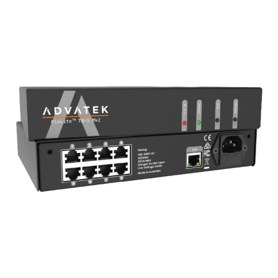
5.3 - Connecting the Transmitter to Receivers Receivers are connected to the transmitter via the RJ45 jacks on the rear panel of the PixLite T8-S Mk2. Each jack is labelled with its output number 1-8. These ports are not network ports, and should not be connected to any networking equipment, as shown Figure 15 below. -
Page 17: Expanded Mode
Figure 16: Connecting Receivers to Transmitter 5.4 - Expanded Mode If your pixels do not have a clock line, you may optionally activate expanded mode on the controller, via the Advatek Assistant. In expanded mode, the clock lines are used as data lines instead. -
Page 18: Network Configuration
6 - Network Configuration 6.1 - Network Layout Figure 17: Network Layout using a Server and Switch Figure 17 shows a typical network topology for the PixLite T8-S Mk2 controller(s) LAN. Installations using multicast sACN will benefit from the use of IGMP Snooping enabled network equipment when there are more multicast universes on the network than any one PixLite is using. -
Page 19: Ip Addressing
Having a router on the network is not mandatory but is useful for IP address management with DHCP (see Section 6.2.1). When IGMP snooping, a router may also be required (depending on your network switch functionality). Figure 18: Network Layout using Only a Server In a single controller installation, it may be preferable to connect the controller directly to the host machine, as shown in Figure... -
Page 20: Using A Switch/Direct
If a static IP address is assigned to the controller, then the power LED will be solid from power up. 6.2.2 - Using a Switch/Direct It may be necessary to connect the controller to a network without a DHCP server or even directly to the host machine instead of using a router. -
Page 21: Forcing The Default Ip Address
Figure 19: PC Network Configuration 6.2.3 - Forcing the Default IP Address In the event that you forget the IP of a controller and you can’t see it in the Advatek Assistant, it can be forced to its default IP. A simple procedure can be employed on power up: 1. -
Page 22: Operation
7 - Operation 7.1 - Start-up Upon applying power, the controller will quickly begin outputting data to the receivers, commanding the pixels to turn off. If no data is being sent to the controller then the pixels will remain turned off until valid data is received. During normal operation, on the controller the green power LED will remain on solid and the red status LED will flash to indicate the controller is running and outputting any received Ethernet data to the receivers. - Page 23 seconds (after the controller is already running) or turn it on remotely from the “Test” tab in the Advatek Assistant. The controller will then enter the test pattern mode, where different test patterns are available as described in the table below. The pattern will display the test pattern on all pixels on each of the pixel outputs.
-
Page 24: Firmware Updates
8 - Firmware Updates The controller is capable of having its firmware updated (new software). An update is typically performed to fix problems or to add new features. To perform a firmware update, ensure that you have your PixLite T8-S Mk2 controller connected to the LAN network as per Section 6.1. -
Page 25: Performing A Recovery Firmware Update
8.2 - Performing a Recovery Firmware Update On the rare occasion that the controller encounters an error with its firmware, a recovery firmware update can be performed. This may be necessary if the firmware update process in Section 8.1 fails. 1. -
Page 26: Specifications
9 - Specifications 9.1 - Operating Specifications The table below specifies the recommended operating conditions for a PixLite T8-S Mk2 controller. Parameter Value/Range Units 100-240 Input Voltage Range V AC (50/60 Hz) Max Current Consumption Ambient Operating Temperature -10 to +60 °C 9.2 - Mechanical Specifications The PixLite T8-S Mk2 controller has dimensions as below. -
Page 27: Fault Protection
9.3 - Fault Protection The PixLite T8- S Mk2 features notable protection from potential damage due to various types of faults. This makes the device extremely robust and reliably able to withstand installation and operation even in harsh environments. ESD protection is present on all data line outputs and all Ethernet input lines. All pixel outputs and the Ethernet input are protected against direct shorts to each other as well as to external voltages of up to +/- 24V. -
Page 28: Troubleshooting
10 - Troubleshooting Generally, troubleshooting requires looking at the LEDs on the front panel. 10.1 - LED Codes Please refer to the table below for condition codes for the onboard status and power LEDs. Status LED (Red) Power LED (Green) Condition Normal operation, Flashing Solid Main application running okay... -
Page 29: No Pixel Control
10.3 - No Pixel Control Check that the correct pixel IC type has been selected in the dropdown box in the Advatek Assistant under the ‘LEDs’ tab. Also check the physical wiring and pinout of the pixels, as well as the output fuses. 10.4 - Other Issues Check the LED codes as per Section... -
Page 30: Disclaimer
11 - Disclaimer If you require support or warranty, please refer to Section 10.4 for information on creating a support ticket. You must be issued with a return authorization by Advatek support staff before returning any product. The PixLite T8- S Mk2 controller is supplied with a 3 - year limited warranty and a repair/replacement guarantee. - Page 31 Certification Relevant Country ETL Listing North America and Canada. Equivalent to UL Listing. Europe North America ICES3 Canada Australia and New Zealand Note: This equipment has been tested and found to comply with the limits for a Class A digital device, pursuant to part 15 of the FCC Rules. These limits are designed to provide reasonable protection against harmful interference when the equipment is operated in a commercial environment.
Need help?
Do you have a question about the xLite T8-S Mk2 and is the answer not in the manual?
Questions and answers