Advertisement
READ BEFORE INSTALLATION and OPERATION
The MS6 SYNC LED Light Module must be properly installed in accordance with this document to ensure
safe installation and operation. Fully read and understand the information contained in this document before
attempting to install or operate the device.
Installation of this device requires a good understanding of automotive electronics , systems and
procedures. It is recommended a trained technician perform the installation.
This product may require drilling of mount holes into the vehicle and the installer MUST ensure
vehicle structural integrity or vital parts not be damaged in the process.
Ensure installed device(s) properly operate simultaneously with existing electronic equipment. Nev-
er wire emergency warning devices on radio communication equipment circuits.
The high intensity of this product's LEDs may have ab adverse effect on human vision resulting in
momentary blindness; do not stare directly into device lights.
Use ONLY soap and water to clean outer lens. Use of chemicals results in premature lens cracking
and/or discolouration resulting in reduced performance. Inspect and replace lens immediately if
cracks or crazing occurs. Never pressure wash device to clean.
Regularly inspect and operate this device to ensure proper performance and safe mounting condi-
tions.
MOUNTING
There are two mounting options to provide exterior and interior vehicle installation.
Flush Mount (Interior/Exterior)
212-2041
Installation and Operation Manual
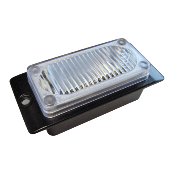
MS6 SYNC FLASHING
LED LIGHT MODULES
Surface Mount (Exterior)
July 31, 2019
Advertisement
Table of Contents

Summary of Contents for D&R ELECTRONICS MS6 SYNC
- Page 1 LED LIGHT MODULES READ BEFORE INSTALLATION and OPERATION The MS6 SYNC LED Light Module must be properly installed in accordance with this document to ensure safe installation and operation. Fully read and understand the information contained in this document before attempting to install or operate the device.
- Page 2 PART NUMBER LEGEND Example: MS6-S-RB-F PART NUMBER LEGEND Customer supplied wires connecting to the power source MUST be rated 125% of maximum operating current. Inline fuses MUST be located at the battery positive terminal and have proper current and voltage rating. Do not use circuit breakers. Adequate grounding is essential to ensure the product operates at maximum efficiency.
- Page 3 LED Module Flash Patterns 1. Strobe Flash PH1 10. Triple Flash Slow PH2 19. Double Burst 2. Strobe Flash PH2 11. Strobe Flash Slow PH1 20. Triple Burst 3. Quad Flash PH1 12. Strobe Flash Slow PH2 21. Slow Fast 1 4.
- Page 4 WARRANTY D & R Electronics warrants its new products to be free from defects in material and workmanship, un- der normal use and service for a period of one year on parts replacement. This warranty applies only to original purchasers acquiring the product directly from D&R Electronics, or its authorized dealers. Warranty will not be recognized without proof of purchase or bill of sale.
Need help?
Do you have a question about the MS6 SYNC and is the answer not in the manual?
Questions and answers