Advertisement
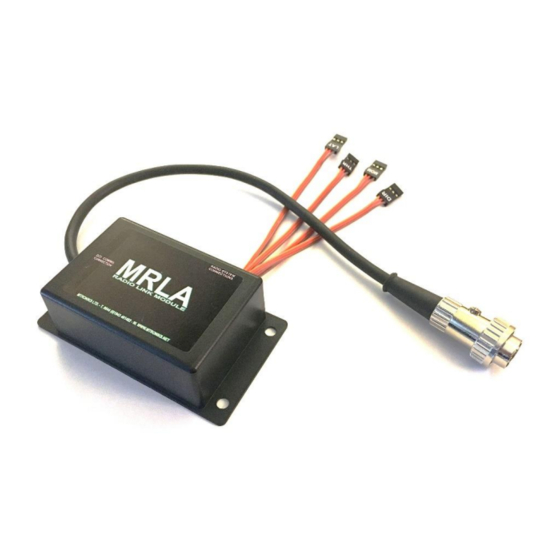
Loco Radio Adaptor (MRLA)
Thank you for purchasing your Mtroniks Loco Radio Adaptor (MRLA), this unit has had the benefit of careful in-
the-field testing and Mtroniks' extensive experience of radio control equipment.
Dimensions: 95.00 x 55.00 x 30.00mm Weight: 100.0g
Caution
Do not plug a battery into your MRLA. The MRLA takes its power from its connection to the ACI/DCI main unit
and then powers the radio receiver. Connecting an additional power source to the MRLA's radio channels
could cause damage to it, or to the ACI/DCI unit that it connects to.
This system is not suitable for use with any system servos. Please contact Mtroniks is this is something you
might want to do.
Do not start the system until your transmitter is switched on, with all its channels in the centre position. It is
strongly advised that each radio channel to be used is tested using the MRLA's Signal Tester mode (see below),
prior to attempting to control a loco.
Safety is crucial, particularly with a potentially very large locomotive model. The loco must be supervised at all
times and fitted with an accessible power isolation switch. When unsupervised, the loco must be left safe and
without the possibility of tampering causing it to become operational.
1
MRLA Manual
Mtroniks Ltd. July 2019
Advertisement
Table of Contents

Summary of Contents for Mtroniks MRLA
- Page 1 Dimensions: 95.00 x 55.00 x 30.00mm Weight: 100.0g Caution Do not plug a battery into your MRLA. The MRLA takes its power from its connection to the ACI/DCI main unit and then powers the radio receiver. Connecting an additional power source to the MRLA’s radio channels could cause damage to it, or to the ACI/DCI unit that it connects to.
- Page 2 Operation Signal Tester Function This function allows the testing of the radio system. All channels that are going to be used to control the MRLA should be tested for appropriate behaviour prior to using the MRLA to control a loco.
- Page 3 In order for the MRLA to be controllable, all radio channels to be used must conform to the below behaviour; • When the radio channel is centred, the MRLA’s Signal Tester LED will light constant Amber. As the channel is moved positively, the LED will begin flashing Green, at the extreme of that movement, the Green LED will become constant.
- Page 4 If the transmitter is left unattended, its signal output will remain static. In this condition, the MRLA will, after a period sound an audible alarm and flash its Alert LED. If action is not taken, then, shortly after, the MRLA will go into Safety Interlock Mode.
Need help?
Do you have a question about the MRLA and is the answer not in the manual?
Questions and answers