Advertisement
Quick Links
IMPORTANT NOTE!
• When using to operate a cruise control, see the special mounting requirements
on the bottom of page 13.
• The GPS-50-2 cannot connect to a BIM-01-2 series.
o The two units cannot send similar data at the same time.
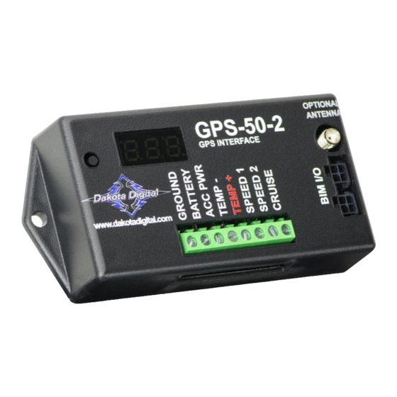
Your new GPS-50-2 includes:
GPS module
Table of Contents:
Product Overview
Installation: Wiring Overview
Installation: Wiring using a BIM cable (no BIM-01-2 present)
Installation: Wiring standalone (individual gauge, or BIM-01-2 present)
Installation Overview
Setup / Clock Setup: VFD3 or VFD3X without a BIM-01-2
Setup / Clock Setup: VHX without a BIM-01-2
Setup / Clock Setup: HDX or RTX without a BIM-01-2
Setup: Standalone speed output only
Setup: Calibration setups for standalone speed only
Cruise Operation
Setup: GPS-50-2 Menu Options
Troubleshooting / Quick tips
Service / Warranty
GPS Speed and Bus Interface Module
Optional Remote
antenna, part 600041.
Contact Dakota Digital
Sales to order.
GPS-50-2
394192 - BIM-XX-2 interface harness
1
Page 2
Page 3
Page 4
Page 5
Page 6
Page 7
Page 8
Page 9
Page 10
Page 11
Page 13
Page 14
Page 18
Page 20
MAN #650519C
Advertisement

Summary of Contents for Dakota GPS-50-2
- Page 1 • When using to operate a cruise control, see the special mounting requirements on the bottom of page 13. • The GPS-50-2 cannot connect to a BIM-01-2 series. o The two units cannot send similar data at the same time.
- Page 2 Product Overview The GPS-50-2 can be used to provide an accurate speedometer signal with a Dakota Digital instrument system as well as many factory and aftermarket speedometers. • Has built in GPS antenna for compact design. • When coupled with a Dakota Digital system with a BIM cable, the unit can provide speed, compass, clock, altimeter, and optional air temp functions.
- Page 3 Installation: Wiring Overview MAN #650519C...
- Page 4 Installation: Wiring using BIM cable Using the BIM cable will be the only way for the VFD/VHX/HDX/RTX dash systems to read: Compass, Altimeter, World Clock, and optional outside air temp. MAN #650519C...
- Page 5 OEM speedometers tend to use SPEED 1. OEM GM cruise controls will like the CRUISE signal when the GPS-50-2 output is set to “4”, while the CRS-2000/3000 modules from Dakota Digital need to be configured for the correct pulses, a square wave signal by turning SW 10 on in the cruise module.
- Page 6 The setup menu will aid in selecting an acceptable mounting location. This should be done in a clear, outside area and not inside a building. Hold the switch beside the GPS-50-2 display while turning the key on. The display will show the current revision code while this is held. Release the switch. Press and release the switch until “”...
- Page 7 Setup VFD3 / VFD3X Using speed from the GPS-50-2 without a BIM-01-x connected ➢ Connect the GPS-50-2 to the instrument system control box with the supplied BIM power/data cable(s). • Hold SW1 (I) for the VFD3 control box, and turn key on.
- Page 8 Using speed from the GPS-50-2 without a BIM-01-x connected GPS-50-2 BIM speed MUST be enabled. See page 15 for details. ➢ Connect the GPS-50-2 to the instrument system control box with the supplied BIM power/data cable(s). • Hold SW1 (I) for the VHX control box, and turn key on.
- Page 9 GPS-50-2 BIM speed MUST be enabled. See page 15 for details. **HDX/RTX systems can be configured with the Dakota Digital app for Apple and Android devices** • Connect the GPS-50-2 to the instrument system control box with the supplied BIM power/data cables. • Entering setup: HDX –...
- Page 10 To eliminate the “PLEASE SET SPEED” messages, the speed calibration can usually be done with the adjust mode without even driving the car. When the GPS-50-2 is sending out the correct test signal, the speedometer should be reading 60 MPH (96 km/h) or be adjusted to 60 MPH (96 km/h).
- Page 11 Aluminum VFD3, and STR boxes = 8,000 PPM - • Once the GPS-50-2 is set to the correct pulse rate, follow the speed setup in the appropriate system manual(s) for the Adjust Mode, or use the app for HDX and RTX.
- Page 12 Set Speed Output / Test mode to 8,000 PPM - • Once the GPS-50-2 is set to the correct pulse rate, follow the speed setup in the appropriate speedometer manual for the Adjust Mode. o Sometimes the speed may not read 60 MPH (96 km/h), adjust so they match.
- Page 13 Cruise control operation with the GPS-50-2 While a transmission or wheel-based speed signal is ideal for operating a cruise control, the GPS-50-2 can be used when this is not available. If the optional remote antenna is not used, special care must be taken in selecting the mounting location for the GPS-50-2 so that it can get a clear view of the satellites.
- Page 14 GPS-50-2 Setup GPS menu table: Menu Sub-Menu Options Default Notes Set BIM ID’s Enable or disable speed data on BIM ...
- Page 15 Having multiple BIMs like the GPS-50-2 and BIM-19-2 (air pressure) could have a conflict with the Altimeter and Tank pressure, as they both use channel 16. Changing the GPS-50-2 Altimeter ID to 9 or 10 will avoid any conflicts with the five pressure channels in the BIM-19-2.
- Page 16 • Press and hold the switch until “ – “ is displayed. • Release the switch. The GPS-50-2 display will show “”, or “” and then blank out. Setup: Altimeter ID number - • Hold the switch beside the GPS-50-2 display while turning the key on.
- Page 17 Both speedometer and GPS must go into setup at the same time. ➢ This adjustment affects ALL three speed outputs • Hold the switch beside the GPS-50-2 display while turning the key on. The display will show the current revision code while this is held. •...
- Page 18 When the key is off the dot in the upper left corner will flash very slowly. If the switch on the GPS-50-2 is held, it will flash rapidly indicating that the key is off.
- Page 19 - Check all connections, avoid crimp connectors Cruise will not hold steady speed - Speed output not matching - Change speed output of GPs-50-2 to match cruise, and/or adjust CRS pulses to match GPS-50-2 - CRS control gain set high...
- Page 20 This Warranty is in lieu of all other expressed warranties or liabilities. Any implied warranties, including any implied warranty of merchantability, shall be limited to the duration of this written warranty. No person or representative is authorized to assume, for Dakota Digital, any liability other than expressed herein in connection with the sale of this product.
Need help?
Do you have a question about the GPS-50-2 and is the answer not in the manual?
Questions and answers