Advertisement
Quick Links
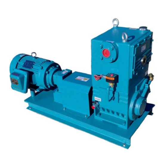
DURAVAC "RP" SERIES
Oil Lubricated, Rotary Piston Vacuum Pumps
Models
RP-35C & RP-50C
INSTALLATION
OPERATION
MANUAL
WARNING
DO NOT OPERATE BEFORE
READING MANUAL
US VACUUM PUMPS LLC
P.O. BOX 909
CANTON, TX USA 75103
TEL: 888-416-7366 FX: 877-416-7599
EMAIL: USVACUUM@EARTHLINK.NET
WWW.USVACUUMPUMPS.COM
Advertisement

Related Manuals for US VACUUM DURAVAC RP Series


Summary of Contents for US VACUUM DURAVAC RP Series
- Page 1 DURAVAC “RP” SERIES Oil Lubricated, Rotary Piston Vacuum Pumps Models RP-35C & RP-50C INSTALLATION OPERATION MANUAL WARNING DO NOT OPERATE BEFORE READING MANUAL US VACUUM PUMPS LLC P.O. BOX 909 CANTON, TX USA 75103 TEL: 888-416-7366 FX: 877-416-7599 EMAIL: USVACUUM@EARTHLINK.NET WWW.USVACUUMPUMPS.COM...
- Page 2 FORWARD This manual contains installation, operation, maintenance and troubleshooting information for the Model RP-35C & RP-50C Rotary Piston Vacuum Pumps. Please read it in its entirety before operating the pump. Our Rotary Piston Vacuum Pumps are designed to ensure safety when used properly. It is the responsibility of the user to follow safety-related warnings, cautions, notes and other requirements described in this manual.
-
Page 3: Safety Precautions
SAFETY PRECAUTIONS CAUTION: When using PVC pipe or any static enhancing material for exhaust piping, make provisions to safeguard against arcing from static electricity. Arcing can ignite oil vapor that may be present. CAUTION: Do not operate the pump without the belt guard properly attached. Operating the pump without the belt guard secured in place exposes people in the vicinity of the pump to risk from rotating drive parts. -
Page 4: Table Of Contents
TABLE OF CONTENTS SAFETY PRECAUTIONS…………………Page 2 INTRODUCTION…………………...………Page 4 PERFORMANCE SPECIFICATIONS…….Page 6 DESCRIPTIONS…………………………….Page 7 GENERAL INFORMATION……….………..Page 8 START-UP……………………………………Page 10 TROUBLESHOOTING………………...……Page 11 PARTS LIST & EXPLODED VIEWS………Page 15 WARRANTY STATEMENT……………..Page 21... -
Page 5: Introduction
CONGRATULATIONS on your purchase of a new Duravac “RP” Series OIL LUBRICATED, Rotary Piston Vacuum Pump from US VACUUM. Please examine the pump for shipping damage, and if any damage is found, report it immediately to the carrier. If the pump is to be installed at a later date make sure it is stored in a Clean, dry location and rotated regularly. - Page 6 PRINCIPLE OF DESIGN The Duravac RP-35/50 series of pumps are of the cam (eccentric) and piston (Slide) type and are Duplex in design. Within the pump, the piston is driven by the cam. The cams are mounted 180 degrees apart on a single shaft so that centrifugal forces of the moving pistons will oppose one another.
-
Page 7: Performance Specifications
INTRODUCTION PERFORMANCE SPECIFICATIONS SPECIFICATIONS Pump Model RP-35C RP-50C Displacement Ultimate Vacuum (Partial pressure) Torr 10 microns (0.010 mm Hg) Motor Pump Speed Oil Capacity Inlet connection 2" Flg 2" Flg Exhaust connection 2" NPT 2" Flg Cooling Media Pump Weight Lbs. - Page 9 =,..- DWN JCM 26-FEB-18 CERTIFIED DRAWING lYPE F C / W 150 /1 ASTM A-197 MALLEA BLE IRON THREADED =,,. US VACUUM PUMPS, LLC PD 26-FEB-18 FITTINGS. 2. CUSTOMER IS RESPONSIBLE FOR PROPER LIFTING PD 26-FEB-18 � EQUIPMENT FOR LIFTING SKID.
- Page 10 The vacuum piping should be designed to insure that no liquids such as condensate or liquid carryover from the process can reach the pump. If this possibility exists, a knock-out liquid separator should be installed…..contact US Vacuum for recommendations. The best piping for the vacuum side of the pump is made up with flanges using neoprene/fiber gaskets or O-rings. Flanges may be welded or threaded to pipe.
- Page 11 VACUUM CONNECTION (cont.) Typical piping arrangement for pump mounted below system (Fig-2) and for the pump mounted above the system (Fig-3) TYPE OF PIPE JOINTS A) Standard steel piping with welded joints makes the best vacuum piping system. B) Copper piping with sweated fittings and joints can also made vacuum tight and has the advantage of providing a neat, clean vacuum installation.
- Page 12 DISCHARGE PIPING It is recommended that the exhaust be piped horizontally a short distance and tied into a vertical exhaust pipe. The vertical exhaust pipe must be at least 1 ft. long and the bottom end of the vertical exhaust pipe be terminated with a plug or drain valve to allow removal of moisture and contaminated oil before it can accumulate sufficiently to drain back into the pump oil reservoir.
- Page 13 ELECTRICAL CONNECTIONS A schematic diagram for the electric motor terminal box is located either inside the junction box cover or on the side of the motor itself. The motor must be connected according to applicable electrical codes Through a fused switch in order to protect the motor against electrical or mechanical overload conditions.
-
Page 14: Start-Up
START-UP 1) Be sure the suctions lines are free of foreign matter and perfectly tight. Use inlet protection screens or drop-out traps on new installations where large welded piping is employed. 2) Make sure the pump discharge is not obstructed 3) Check that the cooling water is connected to the pump and available (If required) 4) Check belt tension. - Page 15 Repair Kit includes bearings, shaft seals, gaskets, o-rings, discharge valves & misc. hardware . NOTE: US Vacuum Pumps LLC is not liable for operational failure due to mistakes made by non-US Vacuum personnel during the installation/operation or the utilization of non-US Vacuum parts Direct Drive Units The RP35C &...
- Page 16 EXCESSIVE HEAT: When the pump is subjected to operating conditions that will cause the oil to be heated above 200 Deg F, the oil will carbonize and become contaminated after a relatively low number of operating hours if standard hydrocarbon oil is used.
-
Page 17: Troubleshooting
TROUBLESHOOTING Before attempting to locate the cause of the of poor ultimate pressure, check the accuracy of the vacuum gauges on the system. TROUBLE Possible cause: The internal parts are worn or The pump does not reach “blank-off” pressure damaged. - Page 18 Possible cause: Cylinder may be flooded with TROUBLE excessive oil due to defective solenoid valve (stuck in open position). Pump runs hot Remedy: Turn pump over by hand to remove ex- Possible cause: Water temperature or flow cessive oil. Check solenoid valve, clean or replace inadequate Possible cause: Oil temperature too low, or Remedy: Check water flow to pump.
- Page 19 RP35/50 VACUUM PUMP � @!- _ , , ,,, � 5 0 55 "-.:: · G � I- I...
- Page 20 RP 35/50 ROTARY PISTON VACUUM PUMP PARTS NAME MATERIAL STEEL WASHER STEEL PUMP SHEAVE IRON MECHANICAL SHAFT SEAL STEEL, VITON, ETC. BOLT STEEL BEARING COVER A IRON O-RING VITON LONG SHAFT SLEEVE STEEL O-RING VITON BEARING STEEL BOLT STEEL STEEL PUMP COVER A IRON SHORT SHAFT SLEEVE A...
- Page 21 BEARING COVER B IRON CHARGE VALVE COPPER, VITON BOLT STEEL GASKET RUBBER O-RING VITON INLET FLANGE STEEL BAFFLE STEEL BOLT STEEL O-RING VITON BOLT STEEL BOLT STEEL SIGHT GLASS STEEL, GLASS O-RING VITON OIL RESERVOIR COVER IRON / ALUMINUM SEPARATOR IRON JOINT COPPER...
- Page 22 No employee or representative of seller other than an officer of US Vacuum Pumps LLC is authorized to change this warranty in any way or grant any other warranty. Any such change by an officer of the company must be in writing.
- Page 23 NOTES...