
Subscribe to Our Youtube Channel
Related Manuals for Steren K-680


Summary of Contents for Steren K-680
- Page 2 IMPORTANT Before using your new Wired control robot arm kit, please read the Before using your new Wired control robot arm kit, please read the following recommendations. following recommendations. • This device is recommended for kids older than 12 years old. •...
- Page 3 ASSEMBLAGE OF REMOTE CONTROL REQUIRED TOOLS Long nose pliers Diagonal cutter Screwdriver CONTENT P1 Metal plate Qty 5 P2 Tapping screw P4 PC Board Qty 9 Qty 1 ENGLISH-03...
- Page 4 PLASTIC PARTS ENGLISH-04...
- Page 5 ASSEMBLY 1.- Insert the piece P3 in the piece C, make a small fold the ribbon cable. ENGLISH-05...
- Page 6 2.- Place the metal plates and screw. 3.- Insert pieces A1, A2, A3 and A4 and A5 in part B. ENGLISH-06...
- Page 7 4.- Assemble and screw parts B and C. 5.- Finished Remote control. ENGLISH-07...
- Page 8 ASSEMBLAGE OF ROBOT REQUIRED TOOLS Long nose pliers Diagonal cutter Screwdriver “D” Battery (4) CONTENT Orange Blue P1 Motor P2 Motor Qty 2 Qty 2 Black Black P3 Motor P4 Gear 32/10T Yellow Qty 1 (Gray) Qty 10 Black P5 Gear 32/10T P6 Gear 32T (Brown) (Blue)
- Page 9 P9 Round shaft P10 Round shaft Qty 9 Qty 1 P11 Tapping screw P12 Tapping screw Qty 5 Qty 11 P13 Tapping screw P14 Tapping screw Qty 19 Qty 12 P15 Machine screw P16 Self tapping screw Qty 10 Qty 4 P17 Self tapping screw P18 Nut Qty 3...
- Page 10 P19 Washer P20 Battery terminal Qty 3 with wire. Qty 1 P21 Battery terminal P22 LED with with connector. wire Qty 1 Qty 1 P23 Sponge P24 Wire Clip Qty 2 Qty 3 P25 PC Board Qty 1 ENGLISH-10...
- Page 11 PLASTIC PARTS ignore ENGLISH-11...
- Page 12 ENGLISH-12...
- Page 13 ASSEMBLY Antes de utilizar su nuevo Kit C From 1 to 4 step must be done twice, to get the pieces M4 and M5 From 1 to 4 step must be done twice, to get the pieces M4 and M5 From 1 to 4 step must be done t From 1 to 4 step must be done t 1.- Place 4 nuts P18 in the piece A2.
- Page 14 2.- Pull the gear system, placing the gear P4, P5, P6 and P7. ENGLISH-14...
- Page 15 3.- Place the motor P1. Black Orange ENGLISH-15...
- Page 16 4.- Finally Put the piece A1 in the previous assembly and screw. So get the pieces M4 and M5. Orange Black ENGLISH-16...
- Page 17 5.- Gearbox assembly for M3. Place 4 nuts P18 in the piece A2. ENGLISH-17...
- Page 18 6.- Pull the gear system, placing the gear P4, P5, P6 and P7. ENGLISH-18...
- Page 19 7.- Place the motor P2. Black Blue ENGLISH-19...
- Page 20 8.- Finally A1 place the piece in the previous assembly and screw. Blue Black ENGLISH-20...
- Page 21 9.- Gearbox assembly for M2. Place 4 nuts P18 in the piece A2. ENGLISH-21...
- Page 22 10.- Pull the gear system, placing the gear P4, P5, P6 and P8. ENGLISH-22...
- Page 23 11.- Place the motor P2. Black Blue ENGLISH-23...
- Page 24 12.- Finally place the piece A1 and screw. Blue Black ENGLISH-24...
- Page 25 13.- Finally parts M2, M3, M4 and M5 were as follows. Blue White Black Blue Black Black Orange Black Black Orange Black Black ENGLISH-25...
- Page 26 14.- Insert 3 pieces B1 in the piece D1. ENGLISH-26...
- Page 27 15.- Place the piece M5 in the previous assembly. Black Orange ENGLISH-27...
- Page 28 16.- Place the battery terminal P20 and P21. Pay attention to the polarity of the terminals. Orange ENGLISH-28...
- Page 29 17.- Accommodate cables battery terminals. Orange ENGLISH-29...
- Page 30 18.- Place the piece F1 and screw. INSTALACION ENGLISH-30...
- Page 31 19.- Place 4 batteries “D” according to the polarity shown in the diagram below. Battery “D” x 4 ENGLISH-31...
- Page 32 20.- Now place the piece in the F7 piece D3 and adjust with the P14 and P19 pieces and place in the previous assembly. ENGLISH-32...
- Page 33 21.- In the piece M4 place the piece F4, use the washers P19 and screw. Black Orange ENGLISH-33...
- Page 34 22.- Place the piece assembled in the previous assembly step 20. ENGLISH-34...
- Page 35 23.- Place two pieces E1 in parts M2 and M3. Then screw. Black Blue Black Blue White Black INSTALACION ENGLISH-35...
- Page 36 24.- Assemble the pieces F2 and F3 and hold it with screws to assemble the previous step. Black White ENGLISH-36...
- Page 37 25.- Place the piece F7 to spare E2 and insert it into the ensable previous assembly and step 22. ENGLISH-37...
- Page 38 26.- Put two round shaft P9 and P10 in the N1 piece. Subsequently assembly system with gear parts P4, P5, P6 and P7 as shown in the diagram below. ENGLISH-38...
- Page 39 27.- Place the motor P3 in the previous assembly. Then insert the piece Black Yellow INSTALACION ENGLISH-39...
- Page 40 28.- Insert the piece N2 and screw. 29.- Insert pieces N5 and N6 who are caring for the same distance between them. For the piece N5 Adjustment with the piece and screw N7. For the piece N6 Adjustment and screw ENGLISH-40...
- Page 41 ENGLISH-41...
- Page 42 30.- Put the pieces N7 and N8 at both ends of the previous assembly and screw. INSTALACION ENGLISH-42...
- Page 43 31.- Detach the role adhere parts P23 and paste it into pieces N3 and N4. Then place it in the previous assembly and screw. INSTALACION ENGLISH-43...
- Page 44 32.- Insert the LED P22 and explore the cable, then adapt the piece N9 on the LED. INSTALACION ENGLISH-44...
- Page 45 33.- Finally place the piece B3, then the piece ensemble with the passage 25 and screw. INSTALACION ENGLISH-45...
- Page 46 34.- Assemble the pieces F6 and F7, then screw on the robot. INSTALACION ENGLISH-46...
- Page 47 35.- Put the pieces and screw E3. INSTALACION ENGLISH-47...
- Page 48 36.- Now place the piece D2 and screw. INSTALACION ENGLISH-48...
- Page 49 37.- Insert the cables with connectors red-black, orange and black-orange in the piece P25. Then attach the pieces F6 and F7, and place it in the assembly and screw. INSTALACION ENGLISH-49...
- Page 50 38.- Place the piece B2 and screw. ENGLISH-50...
- Page 51 39.- Insert connectors L, M1, M2, M3 and M4 Left view Right view ENGLISH-51...
- Page 52 40.- Paste parts P24 and accommodate the cables to avoid entanglements or that may break. INSTALACION ENGLISH-52...
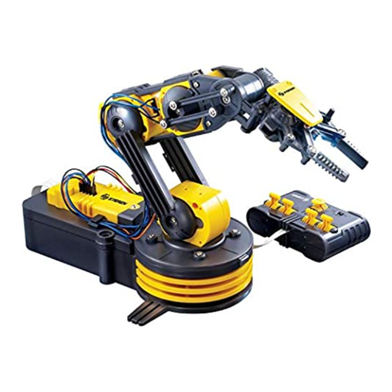
- Page 53 41.- Finished product INSTALACION ENGLISH-53...
- Page 54 ASSEMBLED WITH THE REMOTE CONTROL Once fi nished the previous assembly, insert the cable remote control. INSTALACION ENGLISH-54...
- Page 55 HOW IT WORKS The M1 button opens and closes the pliers, buttons M2, M3 and M4 move the mechanical arm, Button M5 tour based arm. The ON / OFF serves to turn on or off the LED arm. ENGLISH-55...
- Page 56 CIRCUIT DIAGRAM DIAGRAM REMOTE CONTROL ENGLISH-56...
- Page 57 DIAGRAM ROBOT ARM SPECIFICATIONS Input: 6V - - - (4 x D) Maximum pincer opening: 1,77” Vertical clamp movement: 120 Degrees. Vertical arm movement (upper part): 120 Degrees. Vertical arm movement (lower part): 180 Degrees. Horizontal arm movement (base): 270 Degrees. Carrying capacity: 3.5oz.
- Page 58 Part number: K-680 Brand: Steren WARRANTY This Steren product is warranted under normal usage against defects in workmanship and materials to the original purchaser for one year from the date of purchase. CONDITIONS 1.- This warranty card with all the required information, invoice or purchase ticket, product box or package, and product, must be presented when warranty service is required.
- Page 59 RETAILER INFORMATION Name of the retailer Address Product Brand Part number Serial number Date of delivery In case your product fails or have questions, please contact your nearest dealer. If you are in Mexico, please give a call to our Call Center. Call Center 01 800 500 9000...
- Page 61 IMPORTANTE Antes de utilizar su nuevo Kit C Antes de utilizar su nuevo Kit de brazo mecánico con control Antes de utilizar su nuevo Kit de brazo mecánico con control Antes de tili ar s n e o Kit de Antes de tili ar s n e o Kit de remoto alámbrico por favor lea las siguientes recomendaciones remoto alámbrico por favor lea las siguientes recomendaciones...
- Page 62 ENSAMBLE DEL CONTROL REMOTO HERRAMIENTA NECESARIA Pinzas de punta Pinzas de corte Desarmador de cruz CONTENIDO P1 Placa de metal 5 Piezas P2 Tornillo P3 Tarjeta PC 9 Piezas 1 Pieza ESPAÑOL-03...
- Page 63 PARTES DE PLASTICO ESPAÑOL-04...
- Page 64 ENSAMBLE 1.- Inserte la pieza P3 en la pieza C, haga un pequeño doblez al cable plano. ESPAÑOL-05...
- Page 65 2.- Coloque las placas de metal y atornille. 3.- Inserte las piezas A1, A2, A3, A4 y A5 en la pieza B. ESPAÑOL-06...
- Page 66 4.- Ensamble y atornille las piezas B y C. 5.- Control remoto terminado. ESPAÑOL-07...
- Page 67 ENSAMBLE DEL BRAZO MECANICO HERRAMIENTA NECESARIA Pinzas de punta Pinzas de corte Desarmador 4 baterias “D” de cruz CONTENIDO Naranja Azul P1 Motor P2 Motor 2 Piezas 2 Piezas Negro Negro P3 Motor P4 Engrane 32/10T Amarillo 1 Pieza (Gris) 10 Piezas Negro P5 Engrane 32/10T...
- Page 68 P9 Eje P10 Eje 9 Piezas 1 Pieza P11 Tornillo P12 Tornillo 5 Piezas 11 Piezas P13 Tornillo P14 Tornillo 19 Piezas 12 Piezas P15 Tornillo P16 Tornillo Piezas 10 4 Piezas P17 Tornillo P18 Tuerca 3 Piezas 16 Piezas ESPAÑOL-09...
- Page 69 P19 Rondana P20 Terminal de 3 Piezas batería con conector. 1 Pieza P21 Terminal de P22 LED con batería con conector. cable. 1 Pieza 1 Pieza P23 Esponga P24 Clip para cable 2 Piezas 3 Piezas P25 Tarjeta PC 1 Piezas ESPAÑOL-10...
- Page 70 PARTES DE PLASTICO Ignorar ESPAÑOL-11...
- Page 71 ESPAÑOL-12...
- Page 72 ENSAMBLE Antes de utilizar su nuevo Kit C Del paso 1 al 4 se debe realizar doble, para obtener las piezas M4 Del paso 1 al 4 se debe realizar doble, para obtener las piezas M4 Del paso 1 al 4 se debe realizar Del paso 1 al 4 se debe realizar y M5 y M5...
- Page 73 2.- Arme el siguiente sistema de engranes con las piezas P4, P5, P6 y (Café) (Gris) (Negro) (Gris) (Azul) ESPAÑOL-14...
- Page 74 3.- Coloque el motor P1. Negro Naranja ESPAÑOL-15...
- Page 75 4.- Finalmente coloque la pieza A1 en el ensamble anterior y atornille. Asi obtendra las piezas M4 y M5 Naranja Negro ESPAÑOL-16...
- Page 76 5.- Para obtener la pieza M3, Coloque 4 tuercas P18 en la pieza A2 ESPAÑOL-17...
- Page 77 6.- Arme el siguiente sistema de engranes, con las piezas P4, P5, P6 y (Café) (Gris) (Negro) (Gris) (Azul) ESPAÑOL-18...
- Page 78 7.- Coloque el motor P2. Negro Azul ESPAÑOL-19...
- Page 79 8.- Finalmente coloque la pieza A1 en el ensamble anterior y atornille. Finalmente se tendrá la pieza M3. Azul Negro ESPAÑOL-20...
- Page 80 9.- El siguiente ensamble es para obtener la pieza M2. Coloque 4 tuercas P18 en la pieza A2. ESPAÑOL-21...
- Page 81 10.- Arme el siguiente sistema de engranes, con las piezas P4, P5, P6 y P8. (Café) (Gris) (Blanco) (Gris) (Azul) ESPAÑOL-22...
- Page 82 11.- Coloque el motor P2. Negro Azul ESPAÑOL-23...
- Page 83 12.- Finalmente coloque la pieza A1 y atornille. Asi se tendrá la pieza Azul Negro ESPAÑOL-24...
- Page 84 13.- Finalmente las piezas M2, M3, M4 Y M5 quedarán de la siguiente forma. Azul Blanco Negro Azul Negro Negro Naranja Negro Negro Naranja Negro Negro ESPAÑOL-25...
- Page 85 14.- Inserte 3 piezas B1 en la pieza D1. ESPAÑOL-26...
- Page 86 15.- Coloque la pieza M5 en el ensamble anterior. Negro Naranja ESPAÑOL-27...
- Page 87 16.- Coloque la terminal de batería P20 y P21. Ponga atención a la polaridad de las terminales. Naranja ESPAÑOL-28...
- Page 88 17.- Acomode los cables de las terminales de baterías. Naranja ESPAÑOL-29...
- Page 89 18.- Coloque la tapa F1 y atornille. INSTALACION ESPAÑOL-30...
- Page 90 19.- Coloque las 4 baterías tipo “D” de acuerdo a la polaridad mostrada en el siguiente diagrama. Baterías ESPAÑOL-31...
- Page 91 20.- Ahora coloque la pieza F7 en la pieza D3. Posteriormente coloque una rondana P19 y atornille con el ensamble anterior. ESPAÑOL-32...
- Page 92 21.- En la pieza M4 coloque la pieza F4, use las rondanas P19 y atornille. Negro Naranja ESPAÑOL-33...
- Page 93 22.- Coloque la pieza ensamblada anterior en el ensamble del paso 20. INSTALACION ESPAÑOL-34...
- Page 94 23.- Coloque dos piezas E1 en las piezas M2 y M3. Posteriormente atornille. Negro Azul Negro Azul Blanco Negro INSTALACION ESPAÑOL-35...
- Page 95 24.- Ensamble las piezas F2 y F3 y sujetelo con tornillos al ensamble del paso anterior. Negro Blanco INSTALACION ESPAÑOL-36...
- Page 96 25.- Coloque las tapas F7 a las piezas E2. Posteriormente insertelo y atornille en el ensable anterior y el ensamble del paso 22. ESPAÑOL-37...
- Page 97 26.- Coloque dos ejes P9 y P10 en la pieza N1. Posteriormente arme el sistema de engranes con las piezas P4, P5, P6 y P7 como se muestra en el siguiente diagrama. (Negro) (Azul) (Gris) (Cafe) (Gris) ESPAÑOL-38...
- Page 98 27.- Coloque el motor P3 en el ensamble anterior. Posteriormente inserte la pieza F5. Negro Amarillo INSTALACION ESPAÑOL-39...
- Page 99 28.- Inserte la pieza N2 y atornille. 29.- Inserte las piezas N5 y N6 cuidando que esten a la misma distancia entre ambas. Para la pieza N5 Ajuste con la pieza N7 y atornille. Para la pieza N6 solo ajuste y atornille. ESPAÑOL-40...
- Page 100 INSTALACION ESPAÑOL-41...
- Page 101 30.- Coloque las piezas N7 y N8 en ambos extremos del ensamble anterior y atornille. INSTALACION ESPAÑOL-42...
- Page 102 31.- Desprenda el papel adherible de las piezas P23 y peguelas en las piezas N3 y N4. Posteriormente coloquelas en el ensamble anterior y atornille. INSTALACION ESPAÑOL-43...
- Page 103 32.- Inserte el LED P22 y recorra el cable, posteriormente adapte la pieza N9 sobre el LED. INSTALACION ESPAÑOL-44...
- Page 104 33.- Finalmente coloque la pieza B3 y ensamble con la pieza del paso 25 y atornille. INSTALACION ESPAÑOL-45...
- Page 105 34.- Ensamble las piezas F6 y F7, posteriormente atornille en el brazo mecánico. INSTALACION ESPAÑOL-46...
- Page 106 35.- Coloque las piezas E3 y atornille. INSTALACION ESPAÑOL-47...
- Page 107 36.- Ahora coloque la pieza D2 y atornille. INSTALACION ESPAÑOL-48...
- Page 108 37.- Inserte los cables con conectores rojo-negro, naranja y negro-naranja en la pieza P25 y atornille en el brazo mecánico. INSTALACION ESPAÑOL-49...
- Page 109 38.- Coloque la tapa B2 y atornille. ESPAÑOL-50...
- Page 110 39.- Inserte los conectores L, M1, M2, M3 y M4 Vista izquierda Vista derecha ESPAÑOL-51...
- Page 111 40.- Pegue las piezas P24 y acomode los cables para evitar enredos o que se puedan romper. INSTALACION ESPAÑOL-52...
- Page 112 41.- Finalmente asi es como quedará ensamblado el brazo mecánico. INSTALACION ESPAÑOL-53...
- Page 113 ENSAMBLE DEL BRAZO MECANICO CON EL CONTROL REMOTO Una vez terminado el ensamble del brazo mecánico, inserte el cable del control remoto. INSTALACION ESPAÑOL-54...
- Page 114 OPERACION El botón M1 abre y cierra la tenaza, Los botones M2, M3 y M4 mueven el brazo mecánico, El botón M5 gira la base del brazo. El interruptor ON/OFF sirve para encender o apagar el LED del brazo. ESPAÑOL-55...
- Page 115 DIAGRAMAS ELECTRICOS DIAGRAMA DEL CONTROL REMOTO ESPAÑOL-56...
- Page 116 DIAGRAMA DEL BRAZO MECANICO ESPECIFICACIONES Entrada: 6V - - - (4 x D) Altura máxima de la tenaza: 1,77” Movimiento vertical de la tenaza: 120 Grados. Movimiento vertical de la parte superior del brazo: 120 Grados. Movimiento vertical de la parte inferior del brazo: 180 Grados. Movimiento horizontal de la base del brazo: 270 Grados.
- Page 117 1.- Para hacer efectiva la garantía, presente ésta póliza y el producto, en donde fue adquirido o en Electrónica Steren S.A. de C.V. 2.- Electrónica Steren S.A de C.V. se compromete a reparar el producto en caso de estar defectuoso sin ningún cargo al consumidor. Los gastos de transportación serán cubiertos por el proveedor.
- Page 118 Biólogo MaximIno Martínez No. 3408 Int. 3 y 4, San Salvador Xochimanca, México, D.F. 02870, RFC: SPE941215H43 ELECTRONICA STEREN DEL CENTRO, S.A. DE C.V. Rep. del Salvador 20 A y B, Centro, 06000, México. D.F. RFC: ESC9610259N4 ELECTRONICA STEREN DE GUADALAJARA, S.A.
Need help?
Do you have a question about the K-680 and is the answer not in the manual?
Questions and answers