Table of Contents
Advertisement
Quick Links
Introduction
The Yanmar CANplus
economical platform to monitor and control electronically
governed diesel engines. Graphical gauge pages or a single
large analog gauge are displayed on the 4.25" diagonal
LCD. Virtually any SAE J1939 parameter reported by the
ECU (Engine Control Unit) can be displayed including RPM,
coolant temperature, oil pressure, engine hours, voltage and
diagnostic codes. The trans-reflective, backlit display is
clearly readable in both bright sunlight as well as total
darkness and is housed in a rugged IP67 rated housing.
Current alarm conditions are displayed in plain language on
popup messages and can be viewed in the alarm list.
Various diagnostic screens allow detailed investigation of the
CANbus data stream. By accessing the Configuration Menu,
users can customize displayed data to show metric or US
units, display language and various other parameters such
as the full-scale reading of gauges.
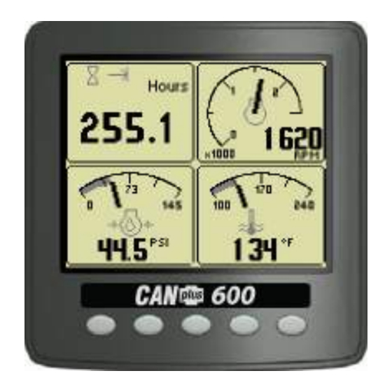
Button 1
Analog Gauge
Pages
Repeated presses
cycle through four
pages of analog
gauges (16 total).
463-3000-09 Initial - 16-May-2008
CANplus and CANplus logo are registered trademarks of LOFA Industries, Inc.
CP600 is a trademarks of LOFA Industries, Inc.
Yanmar
Operation and Troubleshooting
®
600 (CP600™) control panel is an
Button 2
Digital Gauge
Pages
Repeated presses
cycle through four
pages of digital
gauges (16 total).
®
Five buttons access a context dependent button bar when
any button from 1 to 4 is pressed. The graphical menu
structure uses easily understood icons to indicate the
button's current function. After 5 seconds of inactivity the
button bar disappears.
Button 3
Single Analog
Gauge
Repeated presses
cycle through
available analog
gauges.
600 Control Panel
Button 4
Active Alarm
Page
Displays active
alarms including a
plain language
description.
Button 5
Gauge
Adjust
Configures the
parameters
displayed by gauge
pages.
1
Advertisement
Table of Contents
Troubleshooting

Summary of Contents for Yanmar CANplus 600
- Page 1 Yanmar 600 Control Panel ® Operation and Troubleshooting Introduction The Yanmar CANplus ® 600 (CP600™) control panel is an economical platform to monitor and control electronically governed diesel engines. Graphical gauge pages or a single large analog gauge are displayed on the 4.25” diagonal LCD.
-
Page 2: Throttle Control
Remote monitoring can alert maintenance requirements, operational problems, improper operation and location with geo-fence alert. The Web-browser interface allows monitoring an entire fleet of equipment in a central location. Contact Yanmar for more information. When replacement parts are required, Yanmar recommends using replacement parts supplied by Yanmar or parts with equivalent specifications. -
Page 3: Important Safety Information
® Important Safety Information The warnings in this publication are not all inclusive. Yanmar cannot anticipate every potential hazard. Appropriate safety rules and precautions should be followed with any tool, work method or operating procedure. Improper procedures, tools and materials may cause damage or make the equipment unsafe to operate. -
Page 4: Operation
Users can attempt to rectify the fault by restoring factory defaults (see Configuration Menu for details). Contact Yanmar for assistance if the fault persists. After the start-up screen is cleared, the display shows readings on its virtual gauges. Initially the analog... - Page 5 Yanmar 600 Control Panel Operation and Troubleshooting ® Two-State Throttle The optional Two-State Throttle uses a two position rocker switch to adjust the requested engine speed. Pressing the rabbit icon requests the engine to go to Run RPM. Pressing the turtle icon requests the engine to go to Idle RPM.
- Page 6 Yanmar 600 Control Panel Operation and Troubleshooting ® CANplus Display Soft buttons simplify the user interface by displaying a button bar above the buttons when any of the first 4 buttons (buttons 1 to 4, starting from the left) are pressed. Icons on the button bar change to represent the current function of each button.
-
Page 7: Single Analog Gauge
Yanmar 600 Control Panel Operation and Troubleshooting ® Adjust Mode can be disabled in the Configuration Menu to prevent accidental changes. Digital Gauge Pages Digital Gauge Pages display the same data as the Analog Gauge Pages but in digital only format. To... -
Page 8: Active Alarms
Yanmar 600 Control Panel Operation and Troubleshooting ® Active Alarms A flashing popup window is overlaid on the current screen when an active alarm is received. The popup includes a plain language description in addition to the standard SPN/FMI (Suspect Parameter Number/Failure Mode Indicator) pair defined by the SAE J1939 standard. -
Page 9: Configuration Menu
PC program and a hardware adapter that allows total access to the parameters of the panel. For more information about the CANplus Configuration software, please contact Yanmar. Configuration Menu This Configuration Menu allows the user to set various operating parameters such as US or metric units, scale limits for tachometer and service timers. - Page 10 Yanmar 600 Control Panel Operation and Troubleshooting ® Note Most configuration changes take affect immediately. Some such as Idle RPM take affect on the next power up. 463-3000-09 Initial - 16-May-2008...
-
Page 11: Display Menu
Yanmar 600 Control Panel Operation and Troubleshooting ® Display Menu The Display Menu allows the user to configure items affecting how information is displayed. Language Menu Units Menu This menu allows the user to choose between This menu allows the user to set the units used for... - Page 12 Yanmar 600 Control Panel Operation and Troubleshooting ® Gauges Menu Service This menu allows the user to configure aspects of Sets the sixteen (16) service intervals in hours and the gauges displayed. Button 3 selects the resets the service timer. Setting the service interval...
-
Page 13: System Menu
Yanmar 600 Control Panel Operation and Troubleshooting ® System Menu The System Menu allows the user to configure items affecting how the system functions. . Button 4 cycles through the available values for the selected item. The default settings are:... - Page 14 Yanmar 600 Control Panel Operation and Troubleshooting ® Com Viewer J1939 Settings Displays CANbus data received and engine This screen allows adjustments specific to the configuration transmitted by the ECU. J1939 data link. J1939 Viewer Engine Source This screen provides a hexadecimal dump of the Selects which source the display listens to for messages received on the CANbus.
- Page 15 4 the fourth digit. The PIN is entered using button 5 Since Yanmar ECUs use conversion method 4, any setting of this parameter is acceptable. PIN Change This allows changing the PIN. The user is...
- Page 16 Unit part number will not be accessible. VERS Software version number Clearing the PIN requires returning the Flash memory checksum display to Yanmar for service. SOURCE The source of received data LIB1 Low level system library version LIB2 Low level Graphical Display...
- Page 17 Yanmar 600 Control Panel Operation and Troubleshooting ® Throttling Menu The throttling menu allows the user to configure throttle control. The throttling menu allows programming the automatic start/stop throttle profiles as shown in the following diagram. Intermediate RPM Idle RPM...
-
Page 18: Telemetry Menu
Yanmar 600 Control Panel Operation and Troubleshooting ® Telemetry Menu This menu allows configuring the optional telemetry system. Status Telem J1939 Address Displays telemetry and modem status information Defines address the telemetry module is using for retrieved from the telemetry module: CANbus communications. -
Page 19: Service Required
Yanmar 600 Control Panel Operation and Troubleshooting ® Db Viewer The Database Viewer displays and decodes all data monitored by the display. This diagnostic tool allows viewing data not normally displayed. The list can be scrolled using buttons 1 and 2... -
Page 20: Adjusting Lighting And Contrast
Yanmar 600 Control Panel Operation and Troubleshooting ® Data Communications Failure The data communications failure popup icon flashes if the display does not detect data. The warning disappears and normal operation resumes once data is detected. Note Incorrectly configuring the Engine Source address will result in no data available for display. -
Page 21: Typical J1939 Wiring Topology
Yanmar 600 Control Panel Operation and Troubleshooting ® Typical J1939 Wiring Topology Most electronically governed engine installations include a harness with built in J1939 backbone. Use twisted shielded pair with a drain wire for CANbus wiring terminated with 120Ω resistors at each end. The maximum length for the bus is 131 feet (40 m) and stubs should not exceed 39 inches (1m) in length. -
Page 22: Unsealed Connectors
These chemicals may cause seal damage and allow water entry. Use Yanmar provided cavity plugs to seal the connector if wires are removed. Unsealed Connectors For unsealed connectors exposed to the elements, Yanmar recommends using dielectric grease to protect contacts. Warning Yanmar does not recommend using sealant with unsealed connectors. -
Page 23: Battery Circuit Requirements
A reliable dedicated power circuit must be provided for the control system. Yanmar recommends the power connection be made directly to the battery. Grounding through frame members is not recommended! All circuit paths must be capable of carrying any likely fault currents without damage. -
Page 24: Suppression Of Voltage Transients (Spikes)
Warning The installation of voltage transient suppression at the transient source is required. Yanmar follows SAE recommended electrical environment practices. Inductive devices such as relays, solenoids and motors generate voltage transients and noise in electrical circuits. Unsuppressed voltage transients can exceed SAE specifications and damage electronic controls. -
Page 25: Welding On Equipment With Electronic Controls
Yanmar 600 Control Panel Operation and Troubleshooting ® Welding on Equipment with Electronic Controls Proper welding procedures are required to avoid damage to electronic controls, sensors and associated components. The component should be removed for welding if possible. The following procedure must be followed if the component must be welded while installed on equipment with electronic controls. -
Page 26: General Troubleshooting
Yanmar 600 Control Panel Operation and Troubleshooting ® General Troubleshooting For additional information, refer to engine manufacturer troubleshooting guide. No response from starter motor Possible Cause Possible Remedy No battery voltage to starter Verify wiring and battery connection (power and ground) -
Page 27: Engine Troubleshooting
Yanmar 600 Control Panel Operation and Troubleshooting ® Engine Troubleshooting Note Most problems with ECU controlled engines can be pinpointed via the ECU diagnostic messages. Use the display or ECU diagnostic tool to view fault codes. All engine state information and diagnostic codes shown by the CANplus display are provided by the CANbus. -
Page 28: Control System Troubleshooting
Yanmar 600 Control Panel Operation and Troubleshooting ® Control System Troubleshooting Control system does not perform self test Possible Cause Possible Remedy Tripped overcurrent protection Correct fault, replace or reset overcurrent protection Faulty connection to battery Correct battery connections (see Battery Circuit Requirements) -
Page 29: Testing A Warning Or Shutdown
Yanmar 600 Control Panel Operation and Troubleshooting ® Testing a Warning or Shutdown Shutdown simulation with ECU controlled engines requires using the ECU diagnostic tool. Refer to the diagnostic tool documentation to simulate a warning or shutdown. Testing CANbus Most information provided to the CANplus display is sent by the ECU via the CANbus. CANbus is an international data bus used to support SAE J1939. -
Page 30: Diagnostic Trouble Codes (Dtc)
Yanmar 600 Control Panel Operation and Troubleshooting ® Diagnostic Trouble Codes (DTC) CANbus Diagnostic Trouble Codes are a pair of numbers; the Suspect Parameter Number (SPN) and Failure Mode Identifier (FMI). The SPN indicates the faulting subsystem and the FMI identifies the type of failure. - Page 31 Yanmar 600 Control Panel Operation and Troubleshooting ® Data Parameters Monitored This table lists the engine and transmission parameters that are monitored via the CANbus. The parameters can be displayed by the user-configurable gauge pages or the single analog gauge. DB is an abbreviation for the internal database which stores all data transmitted from the engine/transmission.
- Page 32 Yanmar 600 Control Panel Operation and Troubleshooting ® Icon Parameter Gauge Pages Single Gauge Database Intake Manifold Temperature Air Inlet Temperature Exhaust Temperature Auxiliary Temperature 1 Engine ECU Temperature ...
- Page 33 Yanmar 600 Control Panel Operation and Troubleshooting ® Glossary Controller Area Network (also referred to as CANbus); serial communications protocol for electronic engines use Diagnostic Trouble Code; the combination of SPN and FMI that identifies a specific error Engine Control Unit; electronic device responsible for controlling and monitoring engine operation Engine Control Module;...
- Page 34 Yanmar 600 Control Panel Operation and Troubleshooting ® 463-3000-09 Initial - 16-May-2008...
-
Page 35: Software Release History
Yanmar 600 Control Panel Operation and Troubleshooting ® Software Release History 1.44 Initial Yanmar release Document Revision History Initial: 16-May-2008. 463-3000-09 Initial - 16-May-2008... - Page 36 Yanmar 600 Control Panel Operation and Troubleshooting ® 463-3000-09 Initial - 16-May-2008...
- Page 37 Yanmar 600 Control Panel Operation and Troubleshooting ® Typical Schematic The following page shows a typical schematic. Details vary from installation to installation. See the specific schematics for installation for details. 463-3000-09 Initial - 16-May-2008...
- Page 38 Yanmar 600 Control Panel Operation and Troubleshooting ® DSP1 16 AWG Black Power VB- 16 AWG Red Power VB+ B Battery (30) RS232 TX+ RS232 TX- D Starter (50) 14 AWG Black RS232 RX- E Ground (31) RS232 RX+ f CAN Shield...
- Page 39 Yanmar 600 Control Panel Operation and Troubleshooting ® 463-3000-09 Initial - 16-May-2008...
- Page 40 463-3000-09 Initial - 16-May-2008...
Need help?
Do you have a question about the CANplus 600 and is the answer not in the manual?
Questions and answers