Table of Contents

Summary of Contents for PPM CR3551
- Page 1 Point2point Battery Switch and Controller Handbook CR3551 14/11/2016 Pulse Power & Measurement Ltd, 65 Shrivenham Hundred Business Park, Watchfield, Swindon, Wiltshire SN68TY, UK Tel +44 (0)1793 784389 Fax +44 (0)1793 784391 Email sales@ppm.co.uk www.vialite.com...
- Page 2 7368 TABLE OF CONTENTS SAFETY INFORMATION ............... ERROR! BOOKMARK NOT DEFINED. INTRODUCTION ................ERROR! BOOKMARK NOT DEFINED. BATTERY CHARGER ..............ERROR! BOOKMARK NOT DEFINED. 3.1.1 Battery Charging ..................Error! Bookmark not defined. BATTERY OPERATION..............ERROR! BOOKMARK NOT DEFINED. 4.1.1 Battery Discharging ................Error! Bookmark not defined. 4.1.2 Battery Reconditioning ................
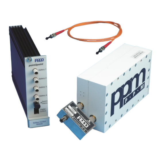
- Page 3 7368 1 Introduction The point2point battery load switch and controller allow the user to remotely control (via multimode fibre optic cable) the DC power applied to a remote FOL (fibre optic link) device. The battery load switch is designed for use with the complete range of point2point equipment.
- Page 4 Multimode Fibre, optical Battery control Singlemode Fibre, optical data carrier Layout for optically controlled battery switches when used in conjunction with PPM shielded batteries. For illustrative purposes only; control module normally resides with receivers in a suitable PPM 19” rack case) h Receivers in a suitable PPM 19”...
-
Page 5: Signal Connections
(ie the centre pin is at a higher voltage than the outer case). The unit is specified for operation with a 14.4V nominal battery pack when operating with PPM point2point shielded FOL. Operation is also possible as a stand-alone unit with a wide input voltages range, see specifications. - Page 6 7368 Pin2 Pin1 Pin8 Pin7 Pinout for Front panel connector and supplied cable (lead length 250mm) Optical port 1 Optical ST connector Multimode optical control fibre for channel 1 Optical port 2 Optical ST connector Multimode optical control fibre for channel 2 Optical port 3 Optical ST connector Multimode optical control fibre for channel 3...
-
Page 7: Maintenance And Fault-Finding Guide
Check that front panel LED on controller is red Incorrect control input status If LED is green, check all control connections are low In the event of any problems or queries about the equipment, contact PPM or your local agent. -
Page 8: Product Warranty
Claims must be made promptly, and during the guarantee period. IMPORTANT: - Please contact both your selling agent and PPM prior to returning any goods for Warranty or Non-Warranty repairs. Goods will not be accepted without a valid return merchandise authorization (RMA). - Page 9 7368 Appendix I Specifications, Battery Load Switch System Parameters (at 25°C, V = 14.4V, I =500mA unless otherwise noted) load Operating voltage range +5V to +30V Operating Current 5A max Voltage drop 50mV max (@500mA) 48mΩ typ On resistance 100mΩ max Time ON >...
- Page 10 7368 Appendix II Specifications, Battery Controller System Parameters (at 25°C unless otherwise noted) Optical output wavelength 820nm Optical output power -12dBm typ (measured using 1m of 62.5/125um cable) -17dBm min AEL Class 1 LED, these devices are considered eye safe. Low = Short circuit (<...
Need help?
Do you have a question about the CR3551 and is the answer not in the manual?
Questions and answers