Table of Contents
Advertisement
Quick Links
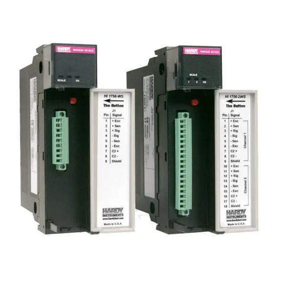
HI 1756-WS & HI 1756-2WS
WEIGH SCALE MODULE
Series A
OPERATION AND INSTALLATION
MANUAL
Corporate Headquarters
9440 Carroll Park Drive, Suite 150
San Diego, CA 92121
Phone: (858) 278-2900
FAX: (858) 278-6700
Web-Site: http://www.hardyinst.com
Hardy Instruments Document Number: 0596-0247-01 Rev K
Copyright November 2000 Hardy Instruments, Inc. All Rights Reserved. Printed in the U.S.A. (941028)
Advertisement
Table of Contents

Summary of Contents for Hardy Instruments A Series
- Page 1 Corporate Headquarters 9440 Carroll Park Drive, Suite 150 San Diego, CA 92121 Phone: (858) 278-2900 FAX: (858) 278-6700 Web-Site: http://www.hardyinst.com Hardy Instruments Document Number: 0596-0247-01 Rev K Copyright November 2000 Hardy Instruments, Inc. All Rights Reserved. Printed in the U.S.A. (941028)
- Page 2 Pacific Standard Time) and weekends Outside the U.S Hardy Instruments has built a network of support throughout the globe. For specific field service options available in your area please contact your local sales agent or our U.S. factory at +1 858-292-2710, Ext. 1757.
-
Page 3: Table Of Contents
Table of Contents Table of Contents OVERVIEW - - - - - - - - - - - - - - - - - - - - - - - - - - - - 1-1 A Brief Description of Chapter 1 - - - - - - - - - - - - - - - - - - - 1-1 About This Manual - - - - - - - - - - - - - - - - - - - - - - - - - 1-1 Description - - - - - - - - - - - - - - - - - - - - - - - - - - - - - 1-2 WAVERSAVER®... - Page 4 HI 1756-WS WEIGH SCALE MODULE Optional Equipment- - - - - - - - - - - - - - - - - - - - - - - - -2-3 1756 RTA (Remote Termination Assembly - - - - - - - - - - -2-3 RTA Cable Assemblies - - - - - - - - - - - - - - - - - - - - -2-3 HI 215IT Series Junction Box - - - - - - - - - - - - - - - - - -2-3 Default Parameters - - - - - - - - - - - - - - - - - - - - - - - - -2-3...
- Page 5 Table of Contents Cal Low Command (CALLOWCMD) - - - - - - - - - - - - - - 4-13 Cal High Command (CALHIGHCMD) - - - - - - - - - - - - - - 4-14 C2 Cal Command (C2CALCMD) - - - - - - - - - - - - - - - - 4-14 Read Weight Cal Command (READWEIGHTCAL) - - - - - - - 4-15 Perform Integrated Technician Tests (WEIGHSYSTEST) - - - - 4-15...
- Page 6 HI 1756-WS WEIGH SCALE MODULE CHAPTER 7 - TROUBLESHOOTING - - - - - - - - - - - - - - - -7-1 A Brief Description of Chapter 7 - - - - - - - - - - - - - - - - - - -7-1 Scale LED stays off when Performing a C2 Calibration with The Button - - - - - - - - - - - - - - - - - - - - - - - - - - - - -7-1 Scale LED is Flashing Red - - - - - - - - - - - - - - - - - - - - -7-1...
- Page 7 Table of Illustrations Table of Illustrations CHAPTER 3 - INSTALLATION - - - - - - - - - - - - - - - - - - - 3-1 POSITIONING THE MODULE FOR INSTALLATION - - - - - - - - 3-2 MODULE RELEASE(S) - - - - - - - - - - - - - - - - - - - - - - - 3-3 MODULE INSTALLED IN CHASSIS- - - - - - - - - - - - - - - - - 3-3 HI 1756-WS WITH DOOR OPEN - - - - - - - - - - - - - - - - - - 3-5...
- Page 8 HI 1756-WS WEIGH SCALE MODULE GUIDELINES FOR INSTABILITIES ON FORMERLY OPERATING SYSTEMS - - - - - - - - - - - - - - - - - - - - - -7-7 GUIDELINES FOR INSTABILITIES ON FORMERLY OPERATING SYSTEMS - ELECTRICAL - - - - - - - - - - - - - -7-8 MECHANICAL STABILITY AND CONFIGURATION SETTINGS - - -7-9...
-
Page 9: Overview
NOTE: WAVERSAVER , C2 NTEGRATED registered trademarks of Hardy Instruments Inc. Before using the product, be sure you understand all cautions, warnings, and safety procedures stated or referenced in this manual. And, to get the best service from this product, follow the practices recommended in this manual. -
Page 10: Description
To calibrate the module you can simply push “The Button” to effect a C2 elec- tronic calibration. C2, Hard (Traditional calibration with weights) is also available for those not using Hardy Instruments C2 certified load sensors. -
Page 11: Waversaver
C2 capabilities (e.g., the HI 1756). Each Hardy Instruments C2-certified load sensor out- puts digital information used for the calibration. The modules reads the sensor outputs and detects the num- ber of active sensors. -
Page 12: Digital Volt Meter (Dvm) - Optional
HI 1756-WS WEIGH SCALE MODULE between the module, Remote Terminal Assembly ® (RTA) and the IT Junction box. If the measured cur- rent deviates more than a ± 10% tolerance, an “Exci- tation Error” bit (Module Status Word bit 9) is set to Digital Volt Meter Requires the HI 215IT Series Junction Box to monitor (DVM) - Optional... -
Page 13: Auto Zero Tracking
Chapter 1 - Overview The ability to read the weight seen by each individual load sensor allows use of this test to make cornering, leveling and load sharing adjustments to the weighing system. AUTO ZERO Auto Zero Tracking automatically adjusts for zero TRACKING weight. - Page 14 HI 1756-WS WEIGH SCALE MODULE...
-
Page 15: Chapter 2 - Specifications
Chapter 2 - Specifications CHAPTER 2 - SPECIFICATIONS A Brief Description of Chapter 2 lists the specifications for the HI 1756-WS Chapter 2 and HI 1756-2WS Weigh Scale Modules. Specifica- tions are listed for the standard instrument and for optional equipment. The specifications listed are designed to assist in the installation, operation and troubleshooting of the instrument. -
Page 16: Common-Mode Voltage Range
HI 1756-WS WEIGH SCALE MODULE Common-Mode 2.5VDC maximum (with respect to earth ground) Voltage Range Backplane Input 5 VDC and 24 VDC Voltage Backplane Current <1 Amp at 5 VDC Load 0.0125 Amps at 24 VDC (with 4-350 Ohm Load Cells Backplane Power <... -
Page 17: Optional Equipment
Chapter 2 - Specifications • mV/V 4 digits to the right of the decimal Optional Equipment 1756 RTA (Remote Hardy Part # -RTA (HI-1756-XX-RTA if ordered sep- Termination arately) Remote Termination supports two (2) sepa- Assembly rate HI 1756-WS weigh scale modules or one (1) HI 1756-2WS weigh scale module. - Page 18 HI 1756-WS WEIGH SCALE MODULE Parameter Default Setting Metric ® 1 Hz WAVERSAVER SpanWeight 10,000.00 CalLowWeight Num Averages ZeroTrackEnable False ROCTimeBase ZeroTolerance AutoZeroTolerance 10.0 lbs MotionTolerance 5.0 lbs Table 2-1: Default Parameters NOTE: * The HI 1756 modules do not have a real time clock, so the year;...
-
Page 19: Chapter 3 - Installation
Weigh Scale Module. Users and service personnel should be familiar with this information before installing or operating the Weigh Scale mod- ule. If you experience any problems installing this equipment, contact Hardy Instruments Inc., Customer Support for assistance. Unpacking Step 1. - Page 20 HI 1756-WS WEIGH SCALE MODULE • Touch a grounded object or surface to rid yourself of any electrostatic dis- charged prior to handling the module. • Handle the module from the bezel in front away from the connector. Never touch the connector pins. •...
-
Page 21: Removing The Module From The Chassis
Chapter 3 - Installation Step 5. The installation is complete. FIG. 3-2 MODULE RELEASE(S) FIG. 3-3 MODULE INSTALLED IN CHASSIS Removing the Module Step 1. Press down on the top and bottom proces- from the Chassis sor releases simultaneously and pull the module out of the chassis. -
Page 22: Installing The Module I/O Connector
HI 1756-WS WEIGH SCALE MODULE Installing the Module I/ O Connector About the Module The I/O Connector at the front of the module connects I/O Connector the module to the Remote Terminal Assembly (- RTA), a load sensor, or the HI 215IT Series Junction Box, depending on how many load sensors are installed in the weighing system. - Page 23 Chapter 3 - Installation receiving information from the load cells or if the relays do not operate correctly. FIG. 3-4 HI 1756-WS WITH DOOR OPEN FIG. 3-5 HI 1756-2WS WITH DOOR OPEN...
-
Page 24: Load Cell Wiring Diagrams
HI 1756-WS WEIGH SCALE MODULE Load Cell Wiring Diagrams Industry Standard Load Cells FIG. 3-6 INDUSTRY STANDARD LOAD CELLS WIRING DIAGRAM Hardy Load Sensor with C2 FIG. 3-7 HARDY LOAD SENSOR/C2 WIRING DIAGRAM... -
Page 25: Hi 1756 Remote Terminal Assembly (Hi 1756-Xx
Chapter 3 - Installation HI 1756 Remote The RTA provides connection points between the HI Terminal module’s cable assembly and the wires from the junc- Assembly tion box(es) or load sensor(s). It comes with a stan- (HI 1756-XX-RT) dard 35 mm Din Rail Mounting and requires at least a 5”... -
Page 26: Rta Cable Assembly
HI 1756-WS WEIGH SCALE MODULE RTA Cable • Six (6) foot cable that connects to the HI 1756- Assembly WS module. FIG. 3-10 RTA CABLE ASSEMBLY - HI 1756WS SINGLE CHANNEL FIG. 3-11 RTA CABLE SCHEMATIC - HI 1756WS SINGLE CHANNEL •... -
Page 27: Hardy Hi 215It Junction Box
Chapter 3 - Installation FIG. 3-13 RTA CABLE SCHEMATIC - HI 1756- 2WS DUAL CHANNEL Hardy HI 215IT Junction Box Load Cell Connector FIG. 3-14 HARDY HI 215IT JUNCTION BOX WIRING DIAGRAM NOTE: When connecting the Hardy HI 215IT Junction Box you must remove the two factory installed jumpers 1&2 and 5&6 on the module install sense lines. - Page 28 HI 1756-WS WEIGH SCALE MODULE 3-10...
-
Page 29: Chapter 4 - Setup4-1
Chapter 4 - Setup CHAPTER 4 - SETUP A Brief Description of Chapter 4 covers the firmware and software settings Chapter 4 used to prepare the module controller for calibration and operation. The Setup procedures require Allen- Bradley’s RS Logix 5000, Allen-Bradley RSLinx™ or RSLinx™... -
Page 30: Leds
HI 1756-WS WEIGH SCALE MODULE LEDS Scale Data Flashing Green Error No Calibration LEDs Steady Green Running (Normal) Steady Red Error Read Failure or Error eeprom write. Contact HI Customer Sup- port Flashing Red Read Convert Error. LED is Off Channel is Inactive OK Module Brief Steady... -
Page 31: Communication Configuration Dialog Box
Chapter 4 - Setup Step 2. Select New Module to display a list of modules. Step 3. Scroll to and select the Generic 1756 mod- ule to open the Module Properties form. Step 4. Enter the following connection parameters in the appropriate fields: •... -
Page 32: Configuration Parameters For The Hi 1765-Ws Module
HI 1756-WS WEIGH SCALE MODULE Configuration With version 2.3 software, the HI 1765-WS module Parameters for the HI can recieve 32 words of the configuration data from a 1765-WS Module PLC upon power-up. These data are used only if the value for Config_rev_num is set to 1 and the parame- ters are sent in the correct format and range. - Page 33 Chapter 4 - Setup Offset (In Parameter Words) Dual Channel Config_rev_num1 * ChanEnabled1 DecimalPoints1 ** Metric1 NumAverages1 Waversaver1 SpanWeight1 CalLowWeight1 ZeroTrackEnables1 AutoZeroTolerance1 MotionTolerance0 TareWeight0 EnableButton0 RocTimeBased0 ZeroTolerance0 Spare1_0 * Must be set to 1 for the other values to apply ** Converts integers to floating-point When the parameters are displayed, they do not appear in the form above.
-
Page 34: Input Data
HI 1756-WS WEIGH SCALE MODULE Input Data This is discrete input data which is a module-defined data type, LOCAL:X:I (where X is the slot number). NOTE: The TimeStamp is a 64-bit integer giving the system time in microseconds. STATUSWORD The module returns a binary statusword where each bit indicates a state or condition within the module. -
Page 35: Discrete Data
Chapter 4 - Setup FIG. 4-4 DISCRETE DATA STATUSWORD bit positions refer to these variables: Word Number Definition ERRORADCONVERT 0x0001 Millivolt return from the load cell system is out of range for the unit. ERRORADFAILURE 0x0002 A/D converter in the unit is no longer responding. -
Page 36: Parameters For The Hi 1756-Ws (-2Ws) Module
HI 1756-WS WEIGH SCALE MODULE Word Number Definition STATUSCMDERROR 0x4000 Output Table Command Failed STATUSCHANENABLED 0x8000 Set if channel is enabled Parameters for the HI 1756-WS (-2WS) Module NOTE: The Glossary at the end of this manual provides addi- tional information about the parameters and other common weigh process definitions. - Page 37 Chapter 4 - Setup Type Parameter Description DINT Waversaver Legal Values are 0-4 0 = 7.5 Hz 1 = 3.5 Hz 2 = 1 Hz 3 = .5 Hz 4 = 0.25 Hz REAL SpanWeight Calibration weight, high, in lbs or kgs REAL CalLowWeight Calibration weight, low, in lbs or kgs...
-
Page 38: Parameters Dialog Box
HI 1756-WS WEIGH SCALE MODULE FIG. 4-5 PARAMETERS DIALOG BOX FIG. 4-6 PARAMETERS DIALOG BOX (CONT’D) 4-10... -
Page 39: Commands
Chapter 4 - Setup Commands Commands are configured in the RSLOGIX 5000 as follows: • Message Type: CIP Generic • Service Code 4c (Hex) • Class Name: 4 • Instance Name: 254 • Object Attribute: None, leave this field blank •... -
Page 40: Zero Command (Zerocmd)
HI 1756-WS WEIGH SCALE MODULE Reply data contains 3 fields • Command (DINT): The command number • Channel (DINT): The channel number • Status (DINT): Status information NOTE: Some commands will produce longer replies. Zero Command The Zero Command requests that the current gross (ZEROCMD) weight be set to zero. -
Page 41: Write Non-Volatile Command (Writenonvolatile)
Chapter 4 - Setup Write Non-Volatile The Write Non-Volatile Command causes all parame- Command ters (including calibration constants) to be saved to (WRITENONVOL the non-volatile memory. ATILE) Command Number: 4 (Hexadecimal) Channel Number: 0 or 1 Number of Elements: 8 Error Return Values: None Reload Non- The Reload Non-Volatile Command causes the weigh... -
Page 42: Cal Low Command (Callowcmd)
HI 1756-WS WEIGH SCALE MODULE Channel Number: 0 or 1 Number of Elements: 8 Error Return Values: None Cal Low Command The Cal Low Command sets the “calLowCount” (CALLOWCMD) parameter to the current A/D average counts when doing a hard calibration. An Integrated Technician function gets called during low calibration. -
Page 43: Read Weight Cal Command Readweightcal
Chapter 4 - Setup Error Return Values: • STATUSWORD - there was a conversion error, weight in motion or an A/D error or all three. • C2FAILNODEVS - detected no C2 load cells. • C2FAILCAPEQ - detected two load cells with different capacities. - Page 44 HI 1756-WS WEIGH SCALE MODULE Structure (ITECHTEST) Structure Item Description DINT command* 0x66 DINT channel* 0 or 1 DINT status* DINT nSensors* Number of load sensors. REAL BaseR Load cell impedance measured during Calibration REAL ReadR Impedance measured at test time DINT TestR Test Result: Good = True, Bad = False...
-
Page 45: Structure (Itechtest)
Chapter 4 - Setup Structure Item Description REAL weight_4** Gross Weight, load cell 4 NOTE: Required Command Data * * Available only with the HI 215IT Junction Box. Search for C2 Searches for C2 Load Sensors Load Sensors (C2SEARCH) Command Number: 0x6E (Hexadecimal) Channel Number: 0 or 1 Number of Elements: 8 Return Values:... -
Page 46: Read Status Of Module (Getstatus)
HI 1756-WS WEIGH SCALE MODULE Return Data: • COMMAND • CHANNEL • STATUS • 9 DINT SERIAL NUMBER Error Return Values: • OUTOFTOLERANCE - No C2 Sensor found. Read Status of Reads the condition of the module. Module (GETSTATUS) Command Number: 0x80 (Hexadecimal) Channel Number: 0 or 1 Number of Elements: 8 NOTE:... -
Page 47: Read Parameters (Readparam)
Chapter 4 - Setup Read Parameters Reads all the parameters. (READPARAM) Command Number: 0x69 (Hexadecimal) Channel Number: 0 or 1 Number of Elements: 8 Return Data: • COMMAND • CHANNEL • STATUS • PARAMETERS (See Table 4-1) Read Live Weight Reads gross weight in units set by the Metric Parame- (READLIVEWEIGHT) ter, either lbs or kgs. -
Page 48: Output Table
HI 1756-WS WEIGH SCALE MODULE Number Command (Hex) TARECMD* WRITENONVOLATILE* RELOADNONVOLATILE* 0x10 GETSTATUS 0x80 ENABLEBUTTONCMD** 0x20 DISABLEBUTTONCMD** 0x40 SETDEFAULTPARAMS 0x94 CALLOWCMD* 0x64 CALHIGHCMD* 0x65 C2CALCMD* 0x66 WRITEPARAM 0x68 READPARAM 0x69 WEIGHSYSTEST 0x6D C2SEARCH 0x6E READC2SERIALNUM 0x70 READLIVEWEIGHT 0x6B NOTE: * These commands can be sent through the output table. -
Page 49: Error Code List
Chapter 4 - Setup The least significant 16 bits are a command for Chan- nel 0, the next 16 bits are a command for Channel 1. Commands are “1 shot”, occurring upon a 0-1 transi- tion. Bit 0x2000 in the STATUSWORD will be set upon completion of the output table comand. -
Page 50: Calibration Setup Procedures
HI 1756-WS WEIGH SCALE MODULE Calibration Setup Procedures Setting the Unit of The Unit of measure can be set to either kilograms or Measure pounds. Any weight value input to the module (e.g. CALLOWWEIGHT, SPANWEIGHT) are in the cur- rently selected units. The unit of measure can be set at any time, not just at calibration. -
Page 51: Setting The Span Weight Value
Chapter 4 - Setup Setting the Span The Span Weight is a reference point derived from an Weight Value actual measured weight. This should not be confused with the Scale Capacity. If you have a 100 pound weight and you place it on the scale, the Span Weight would be 100 pounds. - Page 52 HI 1756-WS WEIGH SCALE MODULE 4-24...
-
Page 53: Chapter 5 - Calibration
Chapter 5 - Calibration CHAPTER 5 - CALIBRATION A Brief Description of Chapter 5 provides the recommended calibration pro- Chapter 5 cedures for the HI 1756 (WS or 2WS) Weigh Scale Module. For the module to work properly, it must be calibrated prior to operation, and it should be re-cali- brated periodically or when not in use for extended periods of time. -
Page 54: Electrical Check Procedures
HI 1756-WS WEIGH SCALE MODULE FIG. 5-1 PROPERLY INSTALLED LOAD CELL W/NO BINDING Electrical Check Procedures Load Cell/Point Step 4. Typical Load Cell/Point Input/Output Input/Output Measurements (EXC & SIG Outputs) Measurements a. The Weigh Module is designed to sup- ply 5 VDC excitation to as many as eight 350 Ohm load cells/points. -
Page 55: Load Check
Chapter 5 - Calibration A zero reference point will vary from system to system depending on the “Dead Load” of the vessel. “Dead Load” is the weight of the vessel and appurte- nances only, with no product loaded. In our example we will assume the dead load to be 500 pounds. -
Page 56: C2 Calibration
HI 1756-WS WEIGH SCALE MODULE • For example: If the ladder logic dis- play reads 100 pounds and a 20 pound weight is placed on the vessel or scale, the ladder logic display should read 120 or some value over 100. •... -
Page 57: The Button" C2 Calibration - Hi 1756-Ws
Chapter 5 - Calibration FIG. 5-3 “THE BUTTON” C2 CALIBRATION - HI 1756-WS FIG. 5-4 “THE BUTTON” C2 CALIBRATION - HI 1756-2WS NOTE: If the module is being calibrated for the first time and you are not sure what parameters to set, use the default parameters which are set by the module at power up. -
Page 58: C2 Calibration Using Ladder Logic
Chapter 4, Setup) Step 2. We have provided a Ladder Logic example explaining how to perform the C2 Calibra- tion. The Ladder Logic example is avail- able on the Hardy Instruments Inc. Web Site: http://www.hardyinst.com Step 3. Click on “Support”. -
Page 59: Hard Calibration Ladder Logic Example
Chapter 5 - Calibration • For more information on the Cal Low Command go to Chapter 4, Setup, page 4-11. Step 3. If you used a weight remove it from the scale. Step 4. Place the high (Span) calibration weight on the scale. - Page 60 Your application may vary and the example may or may not meet your requirements. Step 3. The Hard Calibration Ladder Logic Exam- ple is located at the Hardy Instruments Inc. Web Site. If you have access to the Inter- net: Type the following URL: http://www.hardyinst.com Click on the Support button.
-
Page 61: Chapter 6 - Operating Procedures
Chapter 6 - Operating Procedures CHAPTER 6 - OPERATING PROCEDURES A Brief Description of Chapter 6 covers the operation of the HI 1756 (-WS Chapter 6 and -2WS) Weigh Scale Modules. The Operating Pro- cedures include Reading data transferred to the PLC from the weigh scale module. -
Page 62: Discrete Data
HI 1756-WS WEIGH SCALE MODULE FIG. 6-2 DISCRETE DATA... -
Page 63: Chapter 7 - Troubleshooting
CHAPTER 7 - Troubleshooting CHAPTER 7 - TROUBLESHOOTING A Brief Description of Chapter 7 covers troubleshooting and problem resolu- Chapter 7 tion. Maintenance personnel and users should be familiar with Chapter 7 before attempting to repair the HI 1756-WS or HI 1756-2WS. Scale LED stays off If the scale LED does relight when running C2 Cali- when Performing a C2... - Page 64 HI 1756-WS MANUAL Cmd Passed Run Cmd Cmd a Write Status 0 Parameter? Status = 0? passed Index of return values for Write Parameter 1. CALACTIVE 2. CALYEAR Is Status 3. CALMONTH Positive? 4. CALDAY 5. CALID 6. CALIB TYPE 7.
- Page 65 CHAPTER 7 - Troubleshooting Definition Action Definition Action. Status = -3 Status = 1 Status = -5 Status = 2 Status = -6 Status = 64 Status = -7 Status = 256 Status = -8 FIG. 7-2 COMMAND DEFINITIONS AND ACTIONS Name / Code # Definition Action...
- Page 66 HI 1756-WS MANUAL Name / Code # Definition Action erroreepromwrite B4: Module cannot write (save C4: Contact Customer Support to settings) to non-volatile mem- return module for repair. ory. EEPROM is probably bad. success - 0 Command passed. No errors None outoftolerance -3 1.
-
Page 67: Mechanical Inspection
CHAPTER 7 - Troubleshooting Mechanical Inspection See Fig. 7-1 Keep flexures on the horizontal Vertical flexures should be avoided Do not use flexures to correct for misaligned piping Do not use hose flexures to make right angle bends Non-flexed piping should have an unsupported horizontal run using a ratio of 36 times it's diameter. -
Page 68: Load Sharing And Load Sensor Checkout
HI 1756-WS MANUAL Load Sharing and See Figure 7-4 Load Sensor Checkout Does the mV signal increase in a positive direction. If you receive a negative results, check if load cell is mounted correctly. The arrow goes with the direction of force. If there isn't an arrow, you must manually verify the correct direction. -
Page 69: Guidelines For Instabilities On Formerly Operating Systems
CHAPTER 7 - Troubleshooting Guidelines for See Figure 7-5 Instabilities on Formerly Operating Systems Check for Electrical Stability OK ? Check for Mechanical Stability OK ? Check Configuration settings for Stability OK ? Contact Hardy Instruments Customer Support FIG. 7-5 GUIDELINES FOR INSTABILITIES ON FORMERLY OPERATING SYSTEMS... -
Page 70: Electrical
HI 1756-WS MANUAL Electrical See Figure 7-6 Electrical Physical Grounding - All common equipment share a common ground point. B1.1 Keep the ground cable length to earth ground as short as possible. Install a new ground rod if the cable length is excessive. Cable - Cuts or breaks in the loadcell cable insulation allow moisture to wick B1.2... -
Page 71: Mechanical Stability And Configuration Settings
1,000 to 10,000. (expected stable weight reading). Resolution - Divide the total loadcell capacity, including decimal points, by 30,000. (The amount you can expect to see, but not necessarily stable) Contact Hardy Instruments Customer Support FIG. 7-7 MECHANICAL STABILITY AND CONFIGURATION SETTINGS... - Page 72 HI 1756-WS MANUAL 7-10...
-
Page 73: Index
Index Index Symbols “dead” loads 1-2 “The Button” 1-2 “THE BUTTON” C2 Calibration 5-4 Numerics 1756 RTA (Remote Termination Assembly 2-3 350 Ohm load cells/points 5-2 5 VDC excitation 5-2 A Brief Description of Chapter 2 2-1 A Brief Description of Chapter 3 3-1 A Brief Description of Chapter 4 4-1 A Brief Description of Chapter 5 5-1 A Brief Description of Chapter 6 6-1... - Page 74 HI 1756-WS MANUAL Backplane Input Voltage 2-2 Backplane Power Load 2-2 Before signing 3-1 Binding 5-1 C2 Cal Command (C2CALCMD) 4-14, 4-15 C2 Calibration 5-4 C2 Calibration Input 2-2 C2 Calibration Output 2-2 C2 Calibration Using Ladder Logic 5-6 C2 load sensors 5-4 C2®...
- Page 75 Index ControlLogix I/O 1-2 Conversion Rate 2-1 Customer Support Department 1-1 damaged load sensors 1-4 Dead Load 5-3 Default Parameters 2-3 Description 1-2 Digital Volt Meter 1-4 Digital Voltmeter 2-2 DINT 4-8 discrete input data 6-1 dual channel 1-2 DVM 1-4 DVM readings 1-4 Electrical 7-8 Electrical Check Procedures 5-2...
- Page 76 Hard Calibration 5-6 Hard Calibration Ladder Logic Example 5-7 HARDCALFAILCOUNTS 4-14 Hardy HI 215IT Junction Box 3-9 Hardy Instruments C2 certified load sensors 1-3 Hardy Load Sensor with C2 3-6 HI 1756 Remote Terminal Assembly 3-7 HI 215IT Junction Box 1-4...
- Page 77 Index LEDS 4-2 Load Cell Excitation 2-2 Load Cell Wiring Diagrams 3-6 Load Cell/Point Input/Output Measurements 5-2 Load Check 5-3 Load Sharing and Load Sensor Checkout 7-6 loose connections 3-4 Mechanical Inspection 7-5 Mechanical Stability and Configuration Settings 7-9 Message Type 4-2, 4-11 Model and Serial number 3-1 Module Properties 4-3 mV 1-4...
- Page 78 HI 1756-WS MANUAL Perform Integrated Technician Tests (WEIGHSYSTEST) 4-15 pin-out diagram 3-4 Pre-Calibration Procedures 5-1 Processor Releases 3-2 Read C2 Sensor Serial Number (READC2SERIALNUM) 4-17 Read Live Weight (READLIVEWEIGHT) 4-19 Read Parameters (READPARAM) 4-18 Read Status of Module (GETSTATUS) 4-18 Reading data 6-1 REAL 4-8 Reload Non-Volatile (RELOADNONVOLATILE) 4-13...
- Page 79 Index Setting the Unit of Measure 4-21 Setting the WAVERSAVER Value 4-22 Setting the Zero Tolerance Value 4-22 Setting Up Communications Between the PLC and the HI 1756-WS (- 2WS) 4-2 Setup 1-2 Span Weight 4-22 Span Weight paramete 4-14, 5-7 SPANWEIGHT 4-21 Specifications 1-1 Specifications for a Standard HI 1756-WS 2-1...
- Page 80 HI 1756-WS MANUAL Write Parameters (WRITEPARAM) 4-18 Zero Command (ZEROCMD) 4-12...
-
Page 81: Glossary Of Terms
Glossary of Terms GLOSSARY OF TERMS ACCURACY Closeness of a reading to the actual value of the quan- tity being measured. ALARM Indication of a tolerance deviation. APPURTENANCE Any added equipment other than the weigh vessel, platform scale or feeder. Pipes, Valves etc. AUTO ZERO Automatic version of Zero Tolerance which is the TOLERANCES... - Page 82 HI 1756-WS MANUAL CHANNEL ACTIVE A parameter that turns the channel off/on. If channel is set to 0 it is off or inactive. If channel is set to 1 it is on or active. COMMAND A request made by the host computer (PLC) to per- form an Action.
- Page 83 Glossary of Terms E-MAIL Short for electronic mail, the transmission of mes- sages over communications networks. ENTER KEY This key is used to accept user input into the memory. EPROM Electrically Programmable Read-only Memory. ERROR A message that indicates an unacceptable input has been entered.
- Page 84 HI 1756-WS MANUAL Light Emitting Diode. these are used as status indica- tors. LOAD CELL A device which produces output signal proportional to the applied weight or force. Also called a strain gauge. MENU A set of prompts used to configure the instruments. MENU DRIVEN Operational prompts suppled in common language via the system display to guide an operator through a pro-...
- Page 85 Glossary of Terms equipment against spalshing water, seepage of water, falling or hose-directed water and severe external condensation. NEMA 4X An enclosure that is water tight, dust tight and usable both in doors and outdoors. Will protect the enclosed equipment against splashing water, seepage of water, falling or hose directed water and severe external con- densation.
- Page 86 HI 1756-WS MANUAL PREACT The number of units above or below the set point value of which the relay will trip. Use as an “in flight” compensation value. PREVIOUS KEY A key used to step back through menus. PROMPTS Instructions or options presented in a menu by the instrument.
- Page 87 Glossary of Terms SECURE MEMORY The Secure Memory Module stores and protects vital MODULE (SMM) information from corruption. The SMM also allows the transference of data from one instrument to another with no re-calibration ore re-configuration necessary. SET POINT Ordered weight of a particular ingredient. Weight reading at which a relay will be actuated.
- Page 88 HI 1756-WS MANUAL TRANSMITTER ZERO Value the transmitter puts out with the minimum weight on the load cell. Transistor-Transistor Logic Transmit Data UPDATE RATE Number of times per second a new weight reading is taken. ® WAVERSAVER Setting to remove the effects of ambient vibration from interfering with a weight reading.
Need help?
Do you have a question about the A Series and is the answer not in the manual?
Questions and answers