Table of Contents
Advertisement
Quick Links
Advertisement
Table of Contents

Summary of Contents for Memotech Limited RS232
-
Page 2: Table Of Contents
MEMOTECH RS232 Interface INSTRUCTION MANUAL TABLE OF CONTENTS Introduction Basic mode Terminal mode Direct mode Handshaking Setting up RS232 and Memotext Interface Signal Description Control register Command register Status register ASCII/ZX Character conversions... -
Page 3: Introduction
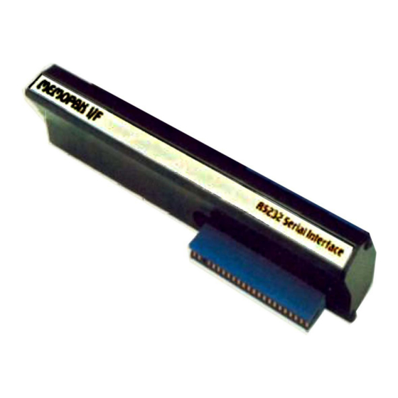
INTRODUCTION The MEMOTECH RS232 Interface can be used in three modes. 1. BASIC 2. TERMINAL 3. DIRECT The BASIC and TERMINAL mode have resident software in the interface pack and it is recommended that one of these modes is used whenever possible. If however neither of these modes is applicable, the interface registers may be accessed directly. - Page 4 Parity Disabled 2 stop bits 9600 Baud After initialising the RS232 in this way, P$ may be cleared since it is no longer needed. It is not normally necessary to clear P$ except in the case of using the TERMINAL mode when no exlra memory is attached. In this case the terminal needs the space and will give an error message if P$ is not cleared .
-
Page 5: Terminal Mode
50 PRINT R$ 2. TERMINAL With the RS232 pack attached, the ZX81 can be used as a terminal. The baud rate parity and stop bits are set up as in the BASIC mode and then the terminal is invoked by calfing USR 10937. - Page 6 RS232 but will not appear on the screen, and any valid character received by the RS232 will be printed on the screen. If the ZX81 cannot recognize a character it will print a question mark.
-
Page 7: Direct Mode
TOGGLES Transmitted Printed on Comments to RS232 screen LPRINT Anything printed on the screen is echoed to a Sinclair or Centronics printer FAST HALF/FULL DUPLEX Shift Toggles whether (AutoIinefeed) NEWLINE NEWLINE (AutoIine generates a CR or feed) CR and LF... -
Page 8: Basic Mode
SETTING UP THE RS232 I/F AND MEMOTEXT Switch off Memotext so that ZX81 powers up into Basic. Set up RS232 parameters (Baud Rate etc.) as in the Basic mode. Switch on Memotext. Press NEW then NEWLINE. Memotext will ask " RS232/CENT? "... -
Page 9: Interface Signal Description
/DSR (input pin 6) is a software transmit inhib. This signal is used by the resident software and is monitored after a byte has been transmitted to ensure that the byte is not aborted. INTERFACE SIGNAL DESCRIPTION /RES (Reset) During system inilialization a low on the /RES input will cause internal registers to be cleared . - Page 10 The table shows that only the Command and Control registers are read/write. The Programmed Reset operation does not cause any data transfers but is used to clear the SY6551 registers. The Programmed Reset is slightly different from the Hardware Reset (RES) and these differences are described in the individual register definitions.
- Page 11 /DSR (Data Set Ready) The DSR input pin is used to indicate to the SY6551 the status of the modem. A low indicates the « ready »state and a high, « not-readyg ». /DSR is a high-impedance input and must not be a no-connect. If unused, it should be driven high or low, but not switched .
-
Page 12: Control Register
Figure 2. Block Diagram CONTROL REGISTER The Control Register is used to select the desired mode for the SY6551. The word length, number of stop bits, and clock controls are alI determined by the Control Register, which is depicted in Figure 3. Figure 3. -
Page 13: Command Register
COMMAND REGISTER The Command Register is used to control Specific Transmit/Receive functions and is shown in Figure 4. Figure 4. Command Register Format 7 6 5 4 3 2 1 0 HARDWARE RESET 0 0 0 0 0 0 0 0 PROGRAM RESET - - - 0 0 0 0 0 STATUS REGISTER... - Page 14 TRANSMIT AND RECEIVE DATA REGISTERS These registers are used as temporary data storage for the 6551 Transmit and Receive circuits. The Transmit Data Register is characterized as follows: - Bit 0 is the leading bit to be transmitted. - Unused data bits are the high-order bits and are "don't care"...
- Page 15 MEMOTECH RS232 INTERFACE CONNECTOR Plugs into Printer /RTS /CTS /DSR /DT READY/DTR /DCD Figure 7. 26 way (13 + 13), Unshrouded Header Plug 25 Way D type Socket 3M Part No 3635 ZX81 REAR CONNECTOR (see ZX81 BASIC Handbook) -Page 13-...
- Page 16 RS232 CABLE CONNECTOR Plugs into Memopak RS232 Interface <-------Pin 1 Connector | 26 WAY RIBBON CABLE 26 Way low-profile Header Socket 3M Part No: 3399 OCRed text file from http:\\zx81.nl PDF from ZX81 comunity. © 2019 -Page 14-...
-
Page 17: Ascii/Zx Character Conversions
I/F ASCII CHARACTERS : -Page 15-... - Page 18 -Page 16-...
- Page 19 -Page 17-...
- Page 20 -Page 18-...
- Page 21 -Page 19-...
- Page 22 -Page 20-...
Need help?
Do you have a question about the RS232 and is the answer not in the manual?
Questions and answers