Advertisement
Quick Links
Sách hướng dẫn sửa chữa
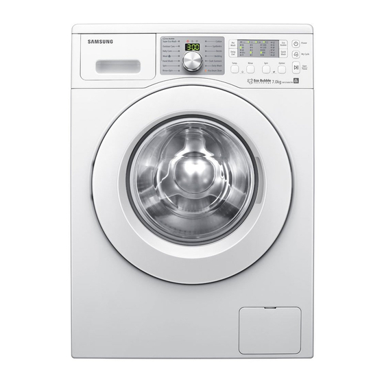
WASHING MACHINE (DRUM)
Refer to the service manual in the GSPN (see the rear cover) for the more information.
WASHING MACHINE
DRUM TYPE
Basic Model : WF9904
(GRIFFIN PROJECT)
Model Name : WF0804*
WF0802*
WF0704*
WF0702*
(SCOUT PROJECT)
Model Code : WF0794W7E9/XSV
1. Khuyến cáo
2. Tính năng và đặc tính sản phẩm
3. Tháo lắp máy
4. Xử lý sự cố
5. Sơ đồ PCB
6. Sơ đồ kết nối dây
7. Tham khảo
NỘI DUNG
Advertisement


Need help?
Do you have a question about the WF0804 Series and is the answer not in the manual?
Questions and answers