Table of Contents
Advertisement
Quick Links
Please read these instructions completely before beginning installation
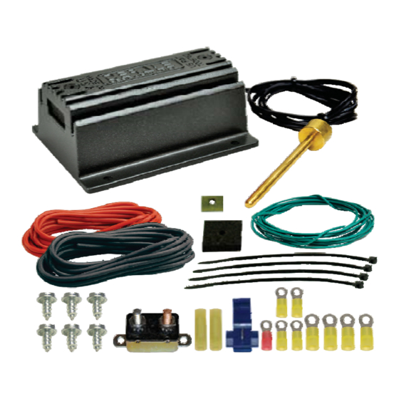
QTY DESCRIPTION
.
1
PWM
Control Module
1
Sensor
1
Foam Pad
1
Retaining Clip
1
50 Amp Circuit Breaker
1
6ft 10
AWG
Red Wire
1
6ft 10
AWG
Black Wire
The Control Module utilizes an auto resetting circuit breaker to
protect the fan(s) and controller circuit. In the event of an electrical
short, the breaker will "trip" and open the connection between the
battery and the controller. If this happens, turn the vehicle off and
let it cool before restarting the system. The breaker will
automatically reset.
MAXIMUM CAPACITY
HOW IT WORKS
The Derale
PWM
Control Module is designed to adjust the electric fan speed
to maintain the optimal engine temperature.
The Control Module has an override circuit available that when activated, will
ramp up the electric fans to 60% running speed. As the engine temperature
increases the fans will increase accordingly.
CONTROL MODULE INSTALLATION
Note 1: If your battery is located in the rear of the car or more than 5ft. from
the controller an additional filter may be required. Please contact technical
support for more information (800) 421-6288 or dp_info@derale.com.
Note 2:
DO NOT use alternator or starter post as a power supply.
1. Take in to consideration probe placement & wire routing requirements.
Avoid mounting near
HOT
in direct contact with any road debris.
2. Using the module as a template, mark and drill four 5/32" holes in the
proper location.
3. Using four #10 sheet metal screws supplied, secure the unit in place.
CIRCUIT BREAKER MOUNTING
1. Choose a convenient location for the Circuit Breaker that is between the
Dual Fan Controller and the Battery.
2. Using the breaker as a template, mark and drill two 5/32" holes in the
proper locations.
3. Using the remaining two #10 sheet metal screws supplied, secure the
Circuit Breaker in place.
SENSOR INSTALLATION
Placement: The Sensor is designed to be installed on the outlet side of the
radiator, sensing the cooler fluid returning to the engine. In some cases where
there is not enough heat to heat the sensor, moving the Sensor to the inlet side
of the radiator may be the solution followed by recalibration.
Note:
be sure the base of the sensor is FIRMLY contacting the radiator fins for
best results. (See Diagram #2)
Warning: Do not install the Thermostat Sensor on the water neck, intake
manifold or cylinder heads.
Installation:
1.
Take the Sensor and thread it clockwise onto the Sensor.
2.
Carefully insert the Sensor assembly into the fins of the radiator until
Sensor is flush with radiator.
3.
Install the Foam Pad onto the Sensor.
4.
Install Retaining Clip onto the Sensor until tight. (See Dia. #2)
(Continues on reverse side)
KIT CONTENTS
QTY DESCRIPTION
.
1
6ft 22
AWG
6
#10 Sheet Metal Screw
2
Yellow Butt Connector
4
Yellow #10 Ring Terminal
4
Yellow #6 Ring Terminal
1
Red #6 Ring Terminal
1
Blue Wire Tap Connector
4
4" Wire Ties
IMPORTANT
: 65
engine components or a location that would be
INSTALLATION INSTRUCTIONS
PWM ELECTRIC FAN CONTROLLER
PART
# 16795 -
Drill
Green Wire
5/32" Drill Bit
Multimeter
Standard Screw Driver
or a 5/16" Nut Driver
AMPS
Inlet
US
Patent 7006762
TOOLS NEEDED
Diagram #1
Cross-flow Radiator
Down-flow Radiator
Inlet
Diagram #2
Sensor
Outlet
Standard Screw Driver
(1/8" wide blade)
Wire Stripper
Wire Crimping Tool
3/32" Allen Wrench
Outlet
Sensor
Sensor
Outlet
Radiator
Foam Pad
Probe
Retaining Clip
Rev. 11172017
16795-InstructionSheet
Advertisement
Table of Contents

Related Manuals for Derale Performance 16795


Summary of Contents for Derale Performance 16795
- Page 1 INSTALLATION INSTRUCTIONS PWM ELECTRIC FAN CONTROLLER PART # 16795 - Patent 7006762 Please read these instructions completely before beginning installation KIT CONTENTS TOOLS NEEDED QTY DESCRIPTION QTY DESCRIPTION Drill Standard Screw Driver 6ft 22 Green Wire Control Module (1/8” wide blade) 5/32”...
- Page 2 Failure to follow instructions can lead to severe damage and personal injury. Derale Performance, Los Angeles, Derale Performance, Los Angeles, 800.421.6288...
- Page 4 ATTENTION If you have any technical questions about this controller please contact Derale Performance. Phone: 800 421-6288 Email: dp_ info@ derale.com...
Need help?
Do you have a question about the 16795 and is the answer not in the manual?
Questions and answers