Table of Contents
Advertisement
Quick Links
Auxiliary Products
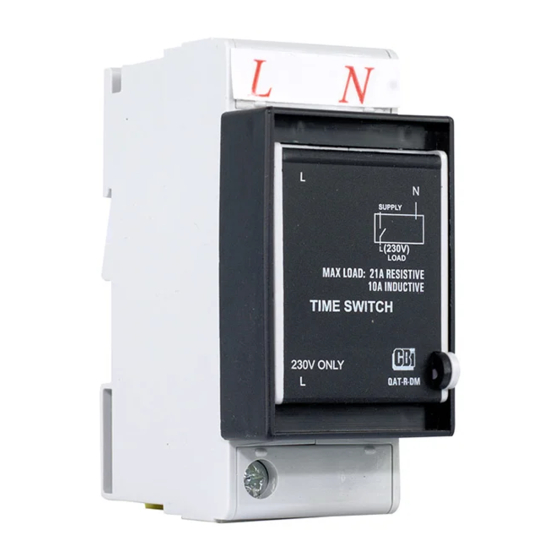
QAT -TRDM – ELECTRONIC TIME SWITCH
Installation and Programming Guide
General
The programmable time switch can be used to automatically control pool pumps, lights,
geysers, etc.
Important Notes
1.
During a power failure, the
standby. After a few hours, the display will turn off completely.
2.
The time switch has a backup power feature which requires 1 hour to charge.
3.
In the event of a power failure, a fully charged time switch will keep time for up to
24 hours.
The programmed schedule is always retained.
4. CBI advises that the time switch be installed by a suitably qualified electrician.
Installation
1.
Isolate supply power before installing time switch.
2.
Install the time switch on either mini rail or DIN rail (remove the escutcheon adapter for DIN).
3.
Connect the time switch according to Figure 1 or Figure 2. Use a suitable contactor (Figure 3) if necessary to switch higher
current. Strictly obey markings for Line and Neutral poles.
4.
Apply power and set the time and desired program schedule.
Supply
L
N
Time
Switch
L
N
Load
Figure 1: DB wiring
Technical Data
Supply Voltage
Maximum Load
Resistive (Geysers, under floor heating, lights)
Inductive (Pool pump, air conditioners)
Contact Endurance
Degree of Ingress Protection (When installed in distribution panel)
Operating Temperature
Single Segment Period
Maximum Period for all Segments
Clock Accuracy
Time Retention (Power Outage)
symbol is displayed and the time switch enters
L
Time
Switch
Neutral
Bar
L
Load
Figure 2: Stand alone wiring
Parameter
Supply
N
L
N
L
loads greater than 21 A resistive or
N
Coil
L1
Time
Contactor
Switch
T1
Figure 3: Wiring a contactor for
10 A inductive
Specification
230 V
50 Hz, 1Ph
RMS
21 A
10 A
20 000 (minimum) Operations
IP40 (not waterproofed)
-20 °C to +55 °C
15 min.
96 x 15 min. Segments
± 3 min. per month
24 h
3990A640 REV C
QAT Guide
OCT 2019
low voltage
Supply
L2 L3 N
T2T3
N
Load
Page 1
Advertisement
Table of Contents

Related Manuals for CBi electric QAT-TRDM

Summary of Contents for CBi electric QAT-TRDM
- Page 1 Auxiliary Products low voltage QAT -TRDM – ELECTRONIC TIME SWITCH Installation and Programming Guide General The programmable time switch can be used to automatically control pool pumps, lights, geysers, etc. Important Notes During a power failure, the symbol is displayed and the time switch enters standby.
- Page 2 Programming Instructions A. HOME TOUCH BUTTONS Use the flesh of your index finger on touch sensitive areas. Default screen. Displays clock and LONG PRESS Press and hold the named touch button for 2 seconds. ON / OFF status. A. Home screen On this screen, the timer is operating according to programmed schedule. The home screen displays the current time.
Need help?
Do you have a question about the QAT-TRDM and is the answer not in the manual?
Questions and answers