Table of Contents
Advertisement
Quick Links
Please record your saws information
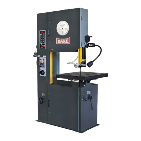
DAKE VERTICAL BAND SAW
Model V-26 E
INSTRUCTION MANUAL
DAKE (Division of JSJ)
724 Robbins Road
Grand Haven, Michigan 49417
616.842.7110
Phone 800-937-3253
616.842.0859
Fax
Web:
www.dakecorp.com
E-mail :
customerservice@dakecorp.com
technicalsupport@dakecorp.com
800-846-3253
Advertisement
Table of Contents
Troubleshooting

Related Manuals for JSJ Dake V-26 E

Summary of Contents for JSJ Dake V-26 E
- Page 1 DAKE VERTICAL BAND SAW Model V-26 E INSTRUCTION MANUAL Please record your saws information DAKE (Division of JSJ) 724 Robbins Road Grand Haven, Michigan 49417 616.842.7110 Phone 800-937-3253 616.842.0859 800-846-3253 Web: www.dakecorp.com E-mail : customerservice@dakecorp.com technicalsupport@dakecorp.com...
-
Page 2: Table Of Contents
DAKE V-26E TABLE OF CONTENTS Forward ....................Installation and set up................Specifications ..................Operational Controls ................Auto-Feed Table ..................Operation: Blade installation ..............Blade Tracking..................Guide Post Adjustment................Guide Adjustment / Holder and Guide............ 11-12 Blade Selection / Type of Blades ............12-13 Tooth Shapes .................. - Page 3 FOREWARD First of all, we would like to take this opportunity to thank you for selecting our Dake V-26 E model vertical Bandsaw. As you know, the vertical bandsaw is a universal saw for contour cutting. Blade selection is important and by choosing the right blade, you can make most any pattern cutting on most any material with this machine.
-
Page 4: Installation And Set Up
11. DO NOT make cuts requiring more power than is available on the machine. 12. Replace warning labels if they become obscured or removed. 13. Make certain the motor switch is in the OFF position before connecting the machine to power. -
Page 5: Forward
CLEANING 1. Remove anti-rust oil. 2. Remove the coating with a clean brush applied with appropriate solvent. 3. When the coating has been softened, remove it with clean rag. POWER SUPPLY 1. Shut off the main power switch ▲ WARNING before connecting cable. - Page 6 Control Panel Guide Post Lifting Wheel Blade Shear Guide Post Locking Knob Welder Panel Work Lamp Grinding Wheel Motor Blade Guide Holder Variable Speed Handwheel Work Table Lifting Eye Table Support Housing Upper Wheel 14/15 Low / High Range Lever, Lower Wheel - 5 -...
-
Page 7: Operational Controls
▲CONTROLS Low/High Range Shift Lever – Located on right side of machine base. Pull toward the front of the machine to shift into the low speed range. Push toward the rear of the machine to shift into the high-speed range. Caution: Do not change the speed range while the machine is running. - Page 8 screws at the rear of the mechanism. Always tighten table bolts before operating the saw Control Panel: 1. Digital Readout- Located on control panel. Shows blade speed in feet per minute. Note: When starting up or changing speed, allow time for the readout to stabilize to the new setting.
-
Page 9: Auto-Feed Table
11. Key Lock Switch– Turn the key to the 12 o’clock position and remove key to lock out power from the control panel. 12. Emergency Stop Switch – Press to stop the machine. Turn knob 90° to reset MANUAL CUTTING, TABLE STATIONARY 1. -
Page 10: Operation: Blade Installation
continuously cutting cycle for light material. SINGLE PIECE CUTTING Switch on “automatic stop selector” knob when the saw is cutting. Machine will stop automatically after the cut is finished. ▲NOTE Depress “manual-reverse” button to back the work piece from the blade if there is any damage or binding to the blade while cutting, or when table travel set up needs adjusting. -
Page 11: Blade Tracking
BLADE TRACKING Blade tracking may be required from time to time depending on the blade size and tension. Disconnect the machine from the power source and open both blade wheel doors. Shift the high-low gearbox lever into the neutral position. Turn the upper blade wheel by hand while observing blade position on the upper blade wheel to determine if adjustment is necessary: a. -
Page 12: Guide Adjustment / Holder And Guide
Figure A Figure B ▲ It may be necessary to open the blade guides, before you adjust the guide post to allow free movement of the guide post. GUIDE HOLDER ADJUSTMENT 1. Loosen inner screws located at the right lower side of guide post with an “L”... -
Page 13: Blade Selection / Type Of Blades
Figure A Figure B The blade guides will wear after time at the front faces. If the blade guides become hard to be properly adjusted, turn the left blade guide over to the right side, as illustrated in the right illustration, and turn the right-side blade guide over to the left side as well. -
Page 14: Tooth Shapes
TYPES OF BLADES Bandsaw blades are available in specific sizes, or in 100 feet coils. They are made from several different metals: 1. Carbon Steel Blade: which are widely used because of their general adaptability for all types of work and the low cost. They are excellent for cutting nonferrous metals and plastics. -
Page 15: Blade Selection Chart
▲ PLEASE NOTE THAT CORRECT BLADE SELECTION IS VERY IMPORTANT TO BANDSAW OPERATING AT FULL POTENTIAL. ALWAYS SELECT A BLADE ACCORDING TO THE MATERIAL SHAPE AND THICKNESS OF THE WORK Always break in the blade per blade manufactures recommendations. SAW BLADE SELECTION MATERIAL SHAPE MATERIAL SHAPE MATERIAL SHAPE... -
Page 16: Saw Speed & Pitch Selector
Please refer to the “Speed & Pitch Selector wheel that is supplied on your saw for speeds and feeds, radius cutting and blade pitch selection. Select saw blades in relationship to the thickness of materials. The following suggestions are a rule of thumb to consider when selecting a blade. A. -
Page 17: Welder Operation
WELDER OPERATION This welder is for occasional use for blade repair and is not intended for welding blades on a regular basis from bulk stock. This welder is best suited for carbon bands but with practice both carbon and bi-metal can also be welded. -
Page 18: Welding Of The Blade
CAUTION: If the saw blade is rusty, the rust must be ground off before the blade is welded. ▲ WELDING 1. Turn pressure knob to “0” position. 2. Butt blade ends together and locate joint in the center between the two electrodes. -
Page 19: Annealing (Bi-Metal)
ANNEALING (Bi-Metal) Set up blade for annealing as mentioned above for carbon blades steps 1 & 2. Heat the band slowly by jogging the annealing switch button until the weld just begins to emit light (this would be the dullest red color) or minute puff of smoke. -
Page 20: Weld Inspection
INSPECION OF THE WELD When the blade is removed from the welder should inspected carefully. The spacing of the teeth should be uniform and the weld should be located in the center of the gullet. Major jaw misalignment is easily noted at this time from the weld appearance. -
Page 21: Trouble Shooting Chart / Saw /Blade / Cutting
MISALIGNED WELD-BLADE ENDS ARE OVERLAPPED (1) Jaw Upset Force Control set for wider blade than used, re-adjust correctly. (2) Blade ends or jaws not aligned correctly. WELD BREAKS WHEN USED (Joint is not complete, “blow holes” in joint) (1) Weld not annealed correctly. (2) Weld has been ground too thin. - Page 22 The annealing job cannot be A. The connection of annealing A. Change an anneal switch made when pushing the anneal switch is loose or broken button B. The fuse is blown B. Change a fuse C. The connection of the electrodes to blade is poor C.
-
Page 23: Maintenance
The blade dulling prematurely A. The blade speed is too fast A. Slow down the blade speed B. The selection of blade is B. Use a proper blade for the improper application C. Feeding rate too fast C. Decrease feeding rate The blade is not cutting straight A. - Page 25 GEAR BOX COMPONENT GUIDE POST COMPONENT 0500 1 * GEAR BOX 1311 GUIDE SUPPORT, UPPER 1312 GUIDE SUPPORT, LOWER 0510 1 * GEAR BOX COVER 303243 1320 BLADE GUIDE 303233 0520 1 * GEAR 1331 BLADE STOPPER, LONG 303251 0521 1 *...
- Page 26 WHEEL COMPONENT CONT. WORK TABLE CONT. 3080 1 * SLIDE BLOCK HOUSING 1090 TABLE SUPPORT HOUSING 3090 1 * SLIDE BLOCK SEAT 1100 GUIDE SUPPORT HOUSING 3100 2 * SLIDE BLOCK GUIDE 1120 RIGHT-HANDED SCREW 3110A 1 * UPPER WHEEL SLIDER 1140 LEFT-HANDED SCREW 3116...
- Page 27 8372 VARIATOR INSTRUCTION 7220 VARIATOR DISK, LOWER * 8422 GEAR BOX INSTRUCTION 7230A VARIATOR DISK, LOWER * 8712 INDICATOR PLATE 7260 SHAFT HOUSING * 8743 TILT INSTRUCTION G6007 BALL BEARING * 9300 UPPER DOOR HINGE G6204 BALL BEARING * 9310 HINGE CP7260 SHAFT HOUSING COMPLETE...
- Page 29 WELDER COMPONENT WORK LAMP COMPONENT 6010 1 * LIMIT SWITCH 6802 1 * WORK LAMP 303250 COMPONENT 303272 Bulb MR 16 12v 20W 6011 1 * INSULATOR 6020 1 * GUIDE BLOCK 6040 1 * HOUSING 6050 1 * STATIONARY JAW SHEAR COMPONENT 6051 1 *...
-
Page 32: Warning / Safety Labels
Warnings • Employer is responsible to perform a hazard/PPE assessment before work activity. • Do not make repairs or adjustments unless you are competent or working under competent supervision. If in doubt consult a qualified technician or engineer • Only use Dake original parts •...