Table of Contents
Advertisement
Quick Links
Advertisement
Table of Contents

Summary of Contents for Vehco Connect5
- Page 1 Connect5 Onboard Installation Guide System diagnostics IMPORTANT: PLEASE READ AND UNDERSTAND ALL THESE INSTRUCTIONS BEFORE COMMENCING INSTALLATION. PLEASE LEAVE THIS MANUAL WITH THE CUSTOMER FOR FUTURE REFERENCE. Version 1.6.1 January 2019 Page 1 of 35...
-
Page 2: Table Of Contents
Before installation ................3 Connect5 system overview ............4 Important information ..............5 Step 1 – Mount Connect5 ..............6 Step 2 – Main Wire Harness ............7 Step 3 – GPS ...................8 Step 4 – FMS ..................9 Step 4 – Without FMS ..............10 Step 5 – Tachograph ..............11 Step 5 –... -
Page 3: Before Installation
All steps in the installation manual are mandatory otherwise the installation will not work! Before starting the installation, make sure you have access to the following; 1. Log in credentials to “Installer WEB” (can be provided by Customer or Vehco Support) o URL: http://install.codriver.com 2. -
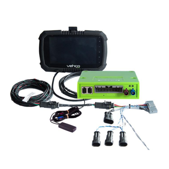
Page 4: Connect5 System Overview
Connect5 system overview Digital Tachograph 100450 100502 100482 Connect5 Road box Id number January 2019 Page 4 of 35... -
Page 5: Important Information
All cables must be mounted so that they can’t be pinched. The cable isolation must not be damaged. All cables coming out of the Connect5 box must be zip-tied to something nearby (max 20cm), this to minimize oscillation in the connector. -
Page 6: Step 1 - Mount Connect5
Step 1 – Mount Connect5 100765 Write down the Connect5 box serial number that begins with “C5-XXX“ (can be found on the box). The “Connect5 box 100765” unit is typically mounted under the dashboard in the vehicle, near the fuse panel. -
Page 7: Step 2 - Main Wire Harness
Reset button 100482 Put the “Main Wire Harness 100482” in the Connect5 box and mount the reset button from the main wire harness near or in the fuse panel. it needs to be accessible by the driver without the need of tools. -
Page 8: Step 3 - Gps
Step 3 – GPS 100479 The internal “GPS/GSM combi antenna 100479” should be placed somewhere on top of the dashboard near the windshield (with the text “GPS” facing the sky). The antenna cables should not be routed near the speakers or the CB radio (Citizens Band Radio) as well as the CB radio antenna wire. -
Page 9: Step 4 - Fms
100502 100503 100482 Connect5 Road box ID First check if the truck has the FMS connector or not. If the vehicle is equipped with the FMS connector, transmission is not always activated. If no transmission, the truck must go to its brands workshop to activate the FMS function. -
Page 10: Step 4 - Without Fms
100502 100482 Connect5 Road box ID First check if the truck have the FMS connector or not. If the vehicle is equipped with the FMS connector, transmission is not always activated. If no transmission, the truck must go to its brands workshop to activate the FMS function. -
Page 11: Step 5 - Tachograph
Route the “D8 cable 100505” from the Connect5 box via the A-piller to the tachograph and connect the brown cable in connector D on pin 8. Mount a secondary “CAN BUS cable 100503”... -
Page 12: Step 5 - Tachograph
Always provide a tachograph connection as described on previous pages. Important: It is REQUIRED to establish both cable connection between the Connect5 unit and the digital tachograph. The CAN connection alone is NOT sufficient to get full functionality. Important: If the tachograph is sealed with a shield above the connectors, it must be removed by an authorised tachograph technician. -
Page 13: Step 6 - Android Screen
Mount the android screen where the customer has given their approval. Fasten the screen using the two screws on the backside of the screen and connect the monitor cables in USB1 on the Connect5 box and the other part of the cable between incoming power and “Main cable 100482”. -
Page 14: Step 7 - System Configuration
(if you don’t know which subcription (SUB-xxxxx) that should be used, please contact the office). 2. Change Road box Id (begins with C5-XXX) to match the Connect5 box and if needed, add Reg nr and Internal nr. 3. Press ”Save”... -
Page 15: Step 8 - System Test With Screen
Step 8 - System test with screen Before using the Connect5 system, a final diagnostic test shall be made. By doing this, you’ve made sure everything is in order before leaving the vehicle. With screen: In the Vehco application, sign in using the Service account... -
Page 16: Step 8 - System Test Without Screen
Step 8 - System test without screen Before using the Connect5 system, a final diagnostic test shall be made. By doing this, you’ve made sure everything is in order before leaving the vehicle. • From your phone/tablet/computer open: http://install.codriver.com • Log in with your credentials •... -
Page 17: Step 9 - Installation Tool
Step 9 - Installation tool The installation form is used to send in the installation information. • Visit on your phone/tablet/computer: http://install.codriver.com • Log in with your credentials • Enter the Company “installer code” 1. From the list, press on the appropriate subscription/vehicle to enter the installation form. - Page 18 Reference information The following pages contains detailed information regarding the installation procedure. January 2019 Page 18 of 35...
-
Page 19: Fms
Mixing up “Direct CAN” and “FMS” connections, can lead to malfunction of the vehicle under certain conditions. If the vehicle is NOT equipped with FMS (illustrated on the upcoming pages) please contact your local Vehco Support, see contact info on the last page of this document. -
Page 20: Truck Information
• On the following pages, you’ll find descriptions of body builder information and FMS interface options. • Body builder information and FMS connection options are based on data/information provided by the different truck manufacturers. Vehco takes no responsibility for the information/data provided by the truck manufacturers. January 2019 Page 20 of 35... -
Page 21: Fms - Volvo Fh/Fm 2002 → 2013
FMS - Volvo FH/FM 2002 → 2013 In this 12-pin connector, the following signals can be • tapped directly: Signal Remarks Connect5 terminal 31 (24V power ground) 1 Always Black Reserved 2 Reserved 12 V+ 3 optional for 24V vehicles... -
Page 22: Fms - Volvo Fh4 2013
• FMS connector is located inside the instrument panel and is labelled “FMS.A”. • In this 12-pin connector, the following signals can be tapped directly: Signal Remarks Connect5 terminal 31 (24V power ground) 1 Always Black Reserved 2 Reserved 12 V+... -
Page 23: Fms - Volvo Fm4 2014
• FMS connector is located under the dashboard on the passenger side and is labeled ”X26” • In this 12-pin connector, the following signals can be tapped directly: Signal Remarks Connect5 terminal 31 (24V power ground) 1 Always Black CAN High 6 Always... -
Page 24: Fms - Volvo Fe/Fl
FMS - Volvo FE/FL → FMS connector is grey and is located inside the instrument Panel, behind the radio and is labelled “X26” X26 – Grey connector Signal Remarks Connect5 terminal 31 (24V power ground) A1 Always Black CAN High A9 Always... -
Page 25: Fms - Scania P-R-T Series → 2009-01-28
--> 9 141 334 São Bernado do Campo --> 3 644 064 • The Scania FMS CAN interface module is situated on the passenger side. CAN is connected via connector C 259. Connector Scania Connect5 C259 CAN-High Blue Blue Pin 21 CAN-Low... -
Page 26: Fms - Scania P-R-T Series (With Rtg) 2009-01-29 2016
3 644 065 --> 1. Fuse for RTG E51. Relay socket for RTG-connection In this green 12-pin connector C137, the following signals can be tapped directly: Signal Pin Remarks Connect5 terminal 31 (24V power ground) 1 Always Black Reserved 2 Reserved 12 V+... -
Page 27: Fms - Scania New Generation 2017
• In the New Generation of Scania trucks, the 12-pin FMS-Connector (C137) is located on the passenger side, behind the main fuse panel. Signal Remarks Connect5 terminal 31 (24V power ground) 1 Always Black CAN High 6 Always Blue CAN low... -
Page 28: Fms - Man
FMS - MAN On newer MAN truck, it’s possible to find the 12-pin green connector behind the tachograph, when connecting here use the following pinout. Signal Pin Remarks Connect5 terminal 31 (24V power ground) 1 Always Black CAN High 6 Always... -
Page 29: Fms - Daf Cf And Xf
CAN signal can be taken from the twisted green and yellow wire in connector 12A. In some cases, there may be a termination resistor, which must be removed when the Connect5 is terminated. DAF wire Connect5 wire DCAN-High Green 3783... -
Page 30: Fms - Mercedes Actros 2 - Bluetec 4 And 5
Bluetec 5 must be mounted on X1 on the PSM module, or from the connector Z3 on the CAN distributor. Valid from 01-10-2007. To connect the CAN-BUS to the Connect5 base unit, mount the Connect5 CAN-Bus cable on the connector X1 on the PSM module. -
Page 31: Fms - Mercedes Actros Mp4 Chassis: Wdb963
FMS - Mercedes Actros MP4 chassis: WDB963 FMS connector is located in the ceiling by the tachograph and is named X167.12. In this connector you will find CAN_H, CAN_L, Battery, Ignition and Ground. Signal Remarks Connect5 terminal 31 (24V power ground) 1 Always Black CAN High... -
Page 32: The Connect5 System Information
Android based display (optional). • The Connect5 base unit includes a computer with Linux operating system. Vehco applications are installed in the unit as well as a GPS and a GSM module for positioning and data communication via GPRS. -
Page 33: Reset The Connect5
Short press on reset button will make the Connect5 to reboot the Linux system and do a normal startup. Hard reboot Press the reset button between 2 and 5 seconds will make the Connect5 do a hard reboot where the power is cut before restarting. LED goes yellow when the hard reboot is initiated. -
Page 34: Led Description
LED description Color Signal Message LED1 Green Constant Self-test OK, network connected "HARDWARE" Blinking Self-test OK, searching for network Yellow Constant Self-test in progress, network connected Blinking Self-test in progress, searching for network Constant General HW Error Blinking Not used System starting LED2 Green... -
Page 35: Contact Information
Contact Information Sweden Technical support support.se@vehco.com +46 31 779 29 79 Norway Germany Technical support Technical support support.no@vehco.com support.de@vehco.com +46 31 779 29 79 +49 431 64 73 88-29 Denmark France Technical support Technical support support.dk@vehco.com support.fr@vehco.com +45 96 96 26 26...
Need help?
Do you have a question about the Connect5 and is the answer not in the manual?
Questions and answers