Table of Contents
Advertisement
Quick Links
Advertisement
Table of Contents

Subscribe to Our Youtube Channel
Related Manuals for Bridgecom Systems BCM-440

Summary of Contents for Bridgecom Systems BCM-440
- Page 1 BCM-440 User Manual By BridgeCom Systems, Inc.
- Page 2 All rights reserved. Printed in the United States of America. Windows is a registered trademark of Microsoft Corporation For Technical Support, please contact: BridgeCom Systems, Inc. 102 NE State Route 92 Highway, Suite C Smithville, MO 64089 Tel: (816)-532-8451 techsupport@BridgeComSystems.com...
-
Page 3: Table Of Contents
TABLE OF CONTENTS CHAPTER 1: INTRODUCTION .................... 5 ........................... 5 ELCOME :..................5 AFETY ARNINGS RECAUTIONS SPECIFICATIONS: ......................8 ........................... 9 EATURES CHAPTER 2: GETTING ACQUAINTED ................10 CHAPTER 3: CONTROLS AND DISPLAY OVERVIEW ............11 : ......................11 RONT ANEL EYPAD LED: .................... - Page 4 APPENDIX A: TERMINAL DESCRIPTION ................27 APPENDIX B: CTCSS/DCS TABLES .................. 28 CTCSS T ..................... 28 VAILABLE ONES WARRANTY AND SERVICE ....................29 FCC STATEMENTS ......................30...
-
Page 5: Chapter 1: Introduction
Do NOT attempt to configure your transceiver while driving. The BCM-440 is designed for 13.8V DC Power. Do not use a 24V battery to power the BCM- 440. Do not place the BCM-440 in excessively dusty, humid, or wet areas. - Page 6 Electronic equipment (e.g. electronic fuel injection, anti-skid braking, and cruise control) in your vehicle may malfunction if not properly protected from the RF energy generated when the BCM-440 is transmitting. Enlist the aid of a knowledgeable Ham or vehicle mechanic in determining if the equipment will perform normally while transmitting.
- Page 7 We recommend that you identify the items listed in the following packing list. If you find that all the items are not present, please contact us. Item Quantity BCM-440 Mobile Radio DC Power Cable w/15 Fuse Mounting Bracket DTMF Microphone...
-
Page 8: Specifications
SPECIFICATIONS: General BCM-440 Number of Channels: Working Voltage: 13.8 V DC +/- 15% Channel Spacing: 25kHz/12.5kHz Weight: 2.4 lbs Frequency Range: 430.0-449.995 MHz (TX) / 400.0 - 470.0 MHz (RX) Dimensions (H x W x D): 1.75 x 6.5 x 6.75” (45 x 165 x 171.5 mm) Frequency Stability: +/- 1.5 ppm (-30 to +60 C) -
Page 9: Features
Features High Quality Mitsubishi Amplifier Module (RA60H4047M1) Selectable power – 5W / 10W / 25W / 50W 250 Channels Narrow and Wide Band Operation High Quality Heavy-Duty DTMF microphone Commercial grade construction 128 x 32 Dot Matrix Graphic LCD ... -
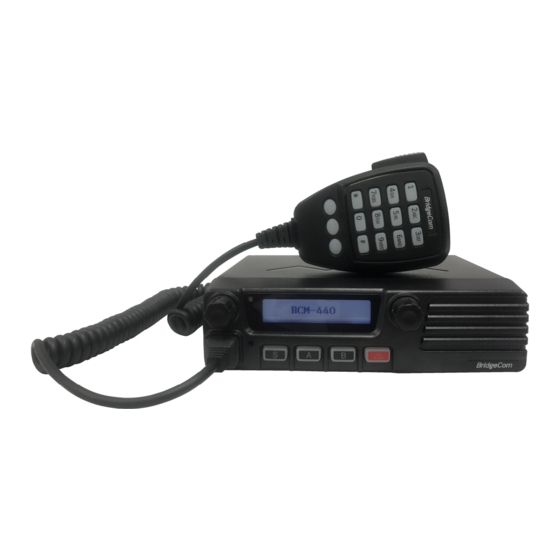
Page 10: Chapter 2: Getting Acquainted
CHAPTER 2: Getting Acquainted Image 2: BCM Radio Front Image 3: BCM Radio Rear Image 4: BCM Radio Display LCD Icons... -
Page 11: Chapter 3: Controls And Display Overview
Tri-Colored Status LED: RED – Transmit / YELLOW – Receive / GREEN – Valid DECODE DTMF Microphone Keypad: The BCM-440 sports a 15-button DTMF (0-9, A,B,C) keypad for operating the radio. The DTMF keys allow for entering frequencies while the radio is in VFO mode. -
Page 12: Chapter 4: Quick Start - Get Me On The Air
CHAPTER 4: QUICK START – GET ME ON THE AIR! We’ve made effort to make this radio as easy to use as possible. Therefore, by way of example this quick start procedure should quickly get you on the air talking on your favorite repeater system. -
Page 13: Rx Ctcss/Dcs Entry
SINE wave icon will be displayed indicating the radio is programmed to decode CTCSS/DCS. You should now be able to communicate radio-to-radio through your local 2 meter repeater! The remainder of this manual will acquaint you with many of the features of the BCM-440. Enjoy! -
Page 14: Chapter 5: Basic Operation
CHAPTER 5: Basic Operation TX 1. Press PTT and face the microphone before talking. The LED should turn RED indicating TX. To ensure good voice quality, the distance between your mouth and the microphone should be between 2.5 and 5 cm. 2. -
Page 15: Alignment Mode
Alignment Mode To enter the Alignment Menu mode, press the ‘A’ button on the radio control head. From this menu you can adjust SQUELCH level, RF output power, TX Voice Dev, TX Sub Dev, DTMF Tone Deviation, and Channel Spacing. To exit the alignment mode menu simply press the ‘A’... -
Page 16: Chapter 6: How-To Function Guide
Chapter 6: HOW-TO Function GUIDE: ● VFO Frequency Entry All VFO frequency entry is done using the DTMF Keypad microphone. The precision of RX frequency you are allowed to enter is based on the FREQ STEP SIZE. For example, if the FREQ STEP SIZE is 10,000 Hz, then you need to enter the first 5 digits of the frequency. -
Page 17: Radio Alignment
ALIGNMENT menu press the ‘A’ button. Changing Power Level The BCM-440 supports four programmable TX Power output settings: 5W, 10W, 20W, and 40W. TX power is adjusted by accessing the alignment menu. The TX Power level applies to VFO mode only. The memory channels have their own TX Power level. -
Page 18: Changing Tx Voice Deviation
Changing TX VOICE DEVIATION The BCM-440 allows for optimizing the TX Voice Deviation levels. The settings are from 0-7. Where Deviation increases from 0 to 7. The voice deviation level is a radio wide setting applied to both VFO and Memory channels. It is recommended a service monitor be used to adjust this setting. -
Page 19: Changing Dtmf Tone Deviation
Changing DTMF Tone Deviation The BCM-440 allows changing the TX DTMF tone Deviation level. The settings are from 0-7. Where deviation increases from 0 to 7. The TX DTMF deviation level is a radio wide setting applied to both VFO and Memory channels. It is recommended a service monitor be used to adjust this setting. -
Page 20: Personality Settings
PERSONALITY SETTINGS Changing Frequency Step Size In VFO mode, the BCM-440 allows for changing the step size as you step through and scan VFO frequencies. The step sizes available are: 5kHz, 10kHz, 12.5kHz, 15kHz, 20kHz, 25kHz, and 30kHz. Make sure the radio is in VFO mode. Press the ‘B’ button the control head to access the personality menu. -
Page 21: Changing Tx Signal
Changing the FREQUENCY OFFSET The BCM-440 provides an easy way to make a quick selection of the 5.0 MHz TX offset required by repeaters: -5.0 MHz, 0 Hz, and +5.0 MHz. In VFO mode, when PTT is pressed, the radio adds the offset to the selected frequency. If the TX frequency is out of range (430.0-449.995), a bad beep is emitted. -
Page 22: Change The Beep Tones On/Off
Press the SELECT button to be able to change the OFFSET. A good beep is emitted. Rotate the SELECT knob clockwise or counter clockwise to find your desired offset. Once found, press the SELECT knob. A good beep is emitted and control goes back to the menu. To exit the personality menu, press the ‘B’... -
Page 23: Scan Operation
VFO mode. A good beep is emitted. SCAN OPERATION The BCM-440 supports two scanning modes. VFO Scan and Memory Scan. Scan is enabled/disabled by pressing the ‘S’ button on the control head. When scan is enabled, the rotating ‘circled S’... -
Page 24: Changing Un-Mute Condition
Changing Un-mute condition This determines what condition allows the radio to un-mute in VFO or MEM Scan mode. The radio may have a RX Signal programmed; yet you may want to use the radio to scan for carrier as you drive into different areas. Having this condition set to un-mute on carrier will allow for defeating the RX Signal option as you look for working stations. -
Page 25: Changing Scan Hang Time
Changing Scan Hang Time The Scan Hang Time is the time spent on the scanned channel after a valid call is received. Make this time long enough to give opportunity to respond to the scanned call. 1. Make sure the radio is in VFO mode. Press the ‘B’ button on the control head to access the personality menu. -
Page 26: Chapter 7: Data Channels And Data Operation
Chapter 7: Data Channels and Data Operation Interfacing a TNC or any data device to the BCM-440, requires use of the 15 pin D-SUB accessory connector. The following table denotes the pin out for what signals are to be applied to the correct pins. -
Page 27: Appendix A: Terminal Description
APPENDIX A: Terminal Description... -
Page 28: Appendix B: Ctcss/Dcs Tables
Appendix B: CTCSS/DCS Tables Available CTCSS Tones 67.0 107.2 165.5 71.9 110.9 173.8 74.4 114.8 179.9 77.0 118.8 186.2 79.7 123.0 192.8 82.5 127.3 203.5 85.4 131.8 210.7 88.5 136.5 218.1 91.5 141.3 225.7 94.8 146.2 233.6 97.4 151.4 241.8 100.0 156.7 250.3... -
Page 29: Warranty And Service
WARRANTY AND SERVICE Limited Warranty This product is warranted by BridgeCom Systems, Inc. to be free of defects in materials and workmanship for a period of one year from the date of purchase. If a defective part causes this product to operate improperly during the one-year warranty period, we will service it to the original owner free of charge if shipped to BridgeCom Systems at the owner’s expense. -
Page 30: Fcc Statements
FCC Statements Warning and Compliance Statement: This device complies with part 15 of the FCC Rules. Operation is subject to the following two conditions: (1) This device may not cause harmful interference, and (2) this device must accept any interference including received interference that may cause undesired operation. WARNING: Modification of this device to receive cellular radiotelephone service signals is prohibited under FCC rules and Federal Law. - Page 31 NOTES:...
- Page 32 BridgeCom Systems, Inc. 102 NE State Route 92 Hwy, Suite C Smithville, M0 64089 816-532-8451 www.BridgeComSystems.com Printed in United States of America...
Need help?
Do you have a question about the BCM-440 and is the answer not in the manual?
Questions and answers