Table of Contents
Advertisement
Quick Links
Advertisement
Table of Contents

Subscribe to Our Youtube Channel
Related Manuals for Audiovox PPC-5050

Summary of Contents for Audiovox PPC-5050
- Page 1 PPC-5050 15” TFT Panel PC Ver 1.x...
- Page 2 The information provided in this document is for reference only. We do not assume any responsibility arising out of the application of the products. This manual is subject to change without any notice. PPC-5050 and ICP are trademark of ICP Electronics Inc.
-
Page 3: Table Of Contents
Chapter 1 Product Information 1.1 General Information 1.2 Product Specifications 1.3 Mechanical Dimension Chapter 2 System Setup 2.1 The Reverse Side of PPC-5050 2.2 The Side of Front Cabinet 2.3 POS-566/370 CPU Board Installation 2.4 Power Supply Installation 2.5 Drive Disk Installation 2.5.1 FDD Installation... -
Page 4: Chapter 1 Product Information
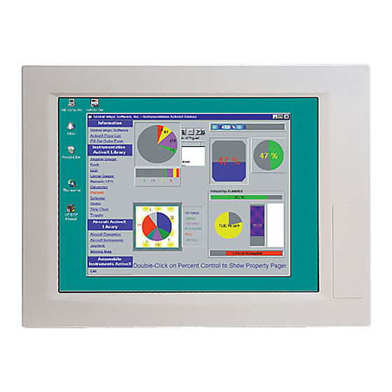
Chapter 1 Product Information 1.1 General Information The PPC-5050, 15" LCD TFT Panel PC, takes advantages of modern flat-panel display, POS-566/370 CPU board, drive spaces and power supply for minimum size. It is an IBM PC/AT compatible computer specially designed to meet the applications for industrial environment. -
Page 5: Product Specifications
1.2 Product Specifications Disk Drive Bay: Support one 2.5" HDD, one slim FDD, and one slim CD-ROM. Best solution for Panel mount man machine interface. Dimensions : Front Panel: 410mm x 309mm x 9mm (WxHxD) Cabinet: 383.6mm x 282.6mm x 93.4mm (WxHxD) LCD Display: 20-pin LCD connector interface to support screen reverse function. - Page 6 Safety: meet UL1950/TUV: EN60950 EMI: meet FCC class B /CISPR:EN 55022 class B/CE: Harmonic EN61000-3-2 Specifications of POS-566 CPU Board: ® The POS-566/566L 450MHz K6-3 / Pentium Processor Multimedia POS Control SBC provides the following specifications: ® ® ® ® ®...
- Page 7 • IrDA port: Support Serial Infrared (SIR) and Amplitude Shift Keyed IR (ASKIR) interface. • Two USB ports: Support dual USB ports for future expansion. • Watchdog timer: Can be set by 1, 2, 10, 20, 110 or 220 seconds period. Reset or NMI is generated when CPU does not periodically trigger the timer.
- Page 8 RJ45 connector for 10BASE-T and 100BASE-TX Full duplex capability, full software driver support. • On CHIP AC97 SIS 7018 • Four high speed Serial ports : three RS-232C, one RS-232C, or RS-422/485 Port • Parallel Ports : Two SPP/EPP/ECP Parallel Ports •...
-
Page 9: Mechanical Dimension
Dimension Mechanical Front Panel: 410mm x 309mm x 9mm (WxHxD) Cabinet: 382.6mm x 282.6mm x 93.4mm (WxHxD) -
Page 10: Chapter 2 System Setup
Chapter 2 System Setup The PPC-5050, 15" LCD TFT Panel PC, is provided complete kit for your operation. The following sections of this chapter will help your installation and maintenance. 2.1 The Reverse Side of PPC-5050 The below diagram shows the reverse side of PPC-5050. - Page 11 2.2.1 The Reverse Side of the Rear Cabinet The below figure indicates the reverse side of the rear cabinet.
- Page 12 2.2 The Side View of PPC-5050 One FDD and CD-ROM are accessible for your operation on the driver frame.
-
Page 13: Pos-566/370 Cpu Board Installation
2.3 POS-566/370 CPU Board Installation To install the POS-566/370 CPU Board, you have to place the board into the cabinet and then fasten it by four screws. -
Page 14: Power Supply Installation
2.4 Power Supply Installation The standard Power Supply for PPC-5050 is ACE-915AP, which has to be fastened to the power bracket by 2 screws , and to be installed in the cabinet by fastening 3 screws as below diagram shown. -
Page 15: Drive Disk Installation
2.5 Drive Disk Installation Following sections will introduce you how to install HDD, FDD and CD-ROM. For the HDD, FDD and CD-ROM are installed in the cabinet, thus you have to open the back cover first if you want to install , upgrade or replace them. 2.5.1 FDD Installation It’s very easy to install the FDD. -
Page 16: Hdd Installation
2.5.2HDD Installation To install the HDD, you have to assemble the HDD to the HDD bracket first. Then, fasten the HDD bracket to the cabinet by 2 screws. -
Page 17: Cd-Rom Installation
2.5.2 CD-ROM Installation To install CD-ROM. You have to assemble the CD-ROM into the bracket, then fasten the CD-ROM Adaptor to the CD-ROM. Finally you have to fasten this unit to the cabinet. -
Page 18: Panel Mounting
2.6 Panel Mounting PPC-5050 is designed for panel mounting. Before mounting the PPC-5050 into panel, you have to check the cut out dimension first. Then mount it into panel by four supporters. Please refer to diagrams below. 286mm 387mm... -
Page 19: Wall Mounting
2.7 Wall Mounting PPC-5050 is suitable for Wall mount. -
Page 20: Arm Mounting
2.8 Arm Mounting PPC-5050 is not only suitable for panel mounting but also for 75/100mm interface pads for arm mounting; and the specification conform to the proposed VESA standard. -
Page 21: Chapter 3 Maintenance
3.1 CPU Board PPC-5050 is equipped with a POS-566/370 CPU card and a 15" LCD. You need to unfasten the some screws and disconnect interface cables to take the CPU Board out for maintenance or upgrading. Please refer to the section 2.2. -
Page 22: Appendix A Exploded Diagram
Appendix A Exploded Diagram ITEM DESCRIPTION PART NO. Q’TY BACK COVER 41022-006023 HDD BRACKET 41011-014700 FDD BRACKET 41011-014800 CDROM BRACKET 41011-014900 DRIVERS BRACKET 41011-014623 CABINET 41002-005823 PCI HOLDER 41005-007723 LCD BRACKET 41017-010023 15” TFT LCD 23000-000028 TOUCH PANEL HOLDER 41014-011402 TOUCH PANEL 48113-333257 FRONT PANEL... -
Page 23: Appendix B Display Interface
Appendix B Display Interface B-1: For POS-566 B-2: For POS-370 ITEM DESCRIPTION PART NO. Q’TY POS-560/370 POS-560(POS-370) LVDS-01 LVDS-01 WIRE CABLE/TOGGLE SW 32100-040400 DF14-20S-1.25C/100cm 32000-022200 NEC:NL-10276BC30-04F 23000-000028... -
Page 24: Appendix C Touch Panel Controller
Appendix C Touch Panel Controller The optional touch screen provides RS232 interface and the wire diagram of the controller is as the below figure shown. Touch Panel Control Board...
Need help?
Do you have a question about the PPC-5050 and is the answer not in the manual?
Questions and answers