3Com AirConnect User Manual
11 mbps wireless lan access point
Hide thumbs
Also See for AirConnect 3Com:
- User manual (40 pages) ,
- Quick start manual (15 pages) ,
- Read me first (2 pages)

Related Manuals for 3Com AirConnect 3Com


Summary of Contents for 3Com AirConnect 3Com
-
Page 1: User Guide
Part No. 09-2045-000 Published December 2000 AirConnect ® Wireless LAN Access Point User Guide Version 2.0 11 Mbps... - Page 2 3Com Corporation 5400 Copyright © 2000, 3Com Corporation. All rights reserved. No part of this documentation may be Bayfront Plaza Santa reproduced in any form or by any means or used to make any derivative work (such as translation, Clara, California transformation, or adaptation) without written permission from 3Com Corporation.
-
Page 3: Table Of Contents
ONTENTS VERVIEW OF IGITAL Introduction AirConnect Network Topologies Peer-To-Peer Network Same-Site Separate Networks Single AP Bridge Multiple-AP Full Coverage Network AirConnect Access Point AP Features PowerBASE-T Radio Basics Cellular Coverage Wireless LAN Service Area 802.1d Spanning Tree Support Site Topography Site Surveys Theory of Operation MAC Layer Bridging... - Page 4 NSTALLING CCESS OINT HARDWARE Introduction Precautions Package Contents Requirements Network Connection 10BASE-T UTP Single Cell Power Options Mounting the AP Flat Surface Wall Mount Ceiling Mount Using the PowerBASE-T LED Indicators Troubleshooting Verify AP Operation Verify Network Wiring and Topology Setting Up Wireless Clients ONITORING TATISTICS...
- Page 5 Installing the Access Point Adding Additional Gateways Configuring the AP Security Adding Allowed Wireless Clients Adding or Deleting a Range of Allowed Wireless Clients Adding or Deleting Disallowed Wireless Clients Enabling or Disabling Encryption Encryption Upgrade Access Codes Special Configuration Considerations Disable Short Preamble System Parameters Radio Frequency Parameters...
- Page 6 Access Point Installation Configuring the AP System Parameters Radio Parameters Configuring PPP PPP Direct Establishing a Connection PPP with Modems Originating AP Answering AP Configuring the SNMP Agent Configuring the Access Control List Range of Wireless Clients Adding Allowed Wireless Clients Removing Allowed Wireless Clients Enable/Disable the ACL Removing All Allowed Wireless Clients...
- Page 7 CCESS OINT PECIFICATIONS ECHNICAL UPPORT Online Technical Services World Wide Web Site 3Com FTP Site Support from Your Network Supplier Support from 3Com Returning Products for Repair NDEX ARRANTY AND EGULATORY 3Com Corporation Limited Warranty Regulatory Compliance Information 3Com End User Software License Agreement OMPLIANCE...
-
Page 9: Overview Of Digital Wireless Networking
Introduction AirConnect deliver high-speed digital wireless networking. This technology provides connectivity between wireless clients and network nodes in a variety of indoor environments, and also provides bridging architecture between wired and wireless network segments. AirConnect is based on the IEEE 802.11B standard, and delivers 11 Mbps data transfer rates. -
Page 10: Same-Site Separate Networks
1: O HAPTER VERVIEW OF IGITAL IRELESS ETWORKING Same-Site Separate In this scenario, as shown in the following figure, Multiple APs can coexist as Networks separate networks at the same site without interference using different network identifiers (wireless LAN service areas). The wireless clients can move within the coverage area of one AP and remain connected, or can roam (if configured to do so) to the coverage area of a different AP, and communicate with the wireless clients associated with that AP. -
Page 11: Single Ap Bridge
AirConnect Network Topologies Single AP Bridge Another possible AirConnect topology is a single AP bridging an Ethernet and wireless network. As shown in the next figure, the AP, wired to a network server or LAN through an Ethernet cable, serves as a network node and provides the link between the server and the wireless clients. -
Page 12: Multiple-Ap Full Coverage Network
1: O HAPTER VERVIEW OF IGITAL Multiple-AP Full This network topology will be used in most enterprise environments: multiple APs Coverage Network wired to an existing LAN to provide complete wireless network coverage. In this scenario, as shown in the following figure, wireless clients can roam seamlessly between different coverage areas and remain connected to the network. -
Page 13: Ap Features
A wireless client communicating with an AP appears on the network as a peer to other network devices, rendering the wireless interface transparent. The AP receives data from its wired interfaces and forwards the data to the proper interface. The AP has connections for wired networks, built-in antennas, and a power supply. It attaches to a wall or ceiling, or can be placed on a flat surface, depending on installation-site requirements. -
Page 14: Radio Basics
1: O HAPTER VERVIEW OF IGITAL IRELESS ETWORKING For details concerning the installation of your PowerBASE-T, see “Using the PowerBASE-T”. Radio Basics AirConnect devices use radio signals to transmit and receive data without wires. You can communicate with the network by establishing radio links between wireless clients and APs. -
Page 15: Cellular Coverage
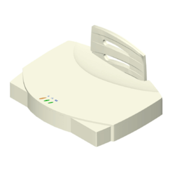
Radio Basics AirConnect devices, like other Ethernet devices, have unique, hardware-encoded Media Access Control (MAC), or IEEE, addresses. MAC addresses determine the device sending or receiving data. A MAC address is a 48-bit number written as six hexadecimal bytes separated by colons. A typical MAC address might be: 00:A0:F8:24:9A:C8 The AP MAC address is printed on the bottom of the unit, as shown below. -
Page 16: Wireless Lan Service Area
1: O HAPTER VERVIEW OF IGITAL IRELESS ETWORKING APs with the same WLAN service area define a coverage area. The wireless client searches for APs with a matching wireless LAN service area and synchronizes with an AP to establish communications. This allows wireless clients within the coverage area to roam between AP cells. -
Page 17: Site Topography
Theory of Operation Site Topography For optimal performance, place wireless clients and APs away from transformers, heavy-duty motors, fluorescent lights, microwave ovens, refrigerators and other industrial equipment. Signal loss can occur when metal, concrete, brick, walls or floors block transmission. Locate antennas in open areas or add additional APs as needed to improve coverage. -
Page 18: Filtering And Access Control
1: O HAPTER VERVIEW OF IGITAL IRELESS ETWORKING Filtering and Access Control The AP provides facilities to limit the wireless clients that associate with it and the data packets that can forward through it. Filters provide network security or improve performance by eliminating broadcast/multicast packets from the radio network. -
Page 19: Bridging Support
The DB-9, 9-pin, RS-232 serial port provides a User Interface (UI) or a Point-to-Point Protocol (PPP) connection. The UI provides basic management tools for the AP. The PPP provides a link between APs using a serial connection. The serial link supports short haul (direct serial) or long haul (telephone line) connections. -
Page 20: Ppp Connection
1: O HAPTER VERVIEW OF IGITAL IRELESS ETWORKING PPP Connection Connecting an AP and a computer with a direct serial link requires the use of a null-modem serial cable. Connecting an AP and computer with modem devices requires the use of straight-through cables between the APs and modems. -
Page 21: Direct-Sequence Spread Spectrum
Direct-Sequence Spread Direct Sequence Spread Spectrum (DSSS) uses a high-speed, non-information Spectrum bearing signal to spread the transmitted information over a segment of the radio frequency band or spectrum. The AirConnect access point uses DSSS for radio communication. Direct-sequence systems communicate by continuously transmitting a redundant pattern of bits called a chipping sequence. -
Page 22: Roaming
1: O HAPTER VERVIEW OF IGITAL and the addition of the AP to the AP table with a proximity classification. An unsuccessful AP packet transmission generates another wireless client probe on the same channel. If the wireless client fails to receive a probe response within the time limits, it repeats the probe process on the next channel in the sequence. -
Page 23: Security
Enabling the extended roaming feature is like giving an individual a local post office forwarding address when leaving home for an extended period. When mail arrives for the individual home address, it is forwarded by the local post office to the current care-of-address. -
Page 24: Http, Html Web Server Support
1: O HAPTER VERVIEW OF IGITAL them to the wireless client and the wireless client goes back to sleep. A DTIM field, also called a countdown field, informs wireless clients of the next window for listening to broadcast and multicast messages. The AP sends the messages following the AP has buffered broadcast or multicast messages for associated wireless clients, it sends the next DTIM with a DTIM Interval value. -
Page 25: Programmable Snmp Trap Support
Changing one AP does not affect the configuration of other APs on the network. Make configuration changes to APs individually. Each AP requires an individual IP address. Programmable SNMP Trap Support The SNMP protocol defines the method for obtaining information about networks operating characteristics and changing router and gateway parameters. -
Page 26: Using The User Interface
1: O HAPTER VERVIEW OF IGITAL Using the User Interface The User Interface (UI) is a text-based maintenance tool integrated into the AP. It provides statistical displays, AP configuration options, and firmware upgrades. Access to the UI requires one of the methods listed in the following table: Method Telnet Client Direct Serial... -
Page 27: Installing Access Point Hardware
Introduction To install an AP, you will have to connect the AP to your network, mount the AP in a location best suited for reception, and provide power to the AP. Precautions Before installing the AP, review the following guidelines and precautions. Package Contents The AP package contains the following items. -
Page 28: Network Connection
2: I HAPTER NSTALLING CCESS Network Connection Locate the Ethernet port and power plug on the back of the AP, as shown by items 2 (power plug) and 3 (Ethernet port) in the figure below. Item 1 is the serial port. Ethernet configurations vary according to the environment. -
Page 29: Mounting The Ap
Mounting the AP The AP can be mounted in any number of locations, some of which are shown below. Flat Surface To mount an AP on a flat surface, place the AP so that it rests on the four rubber pads on its underside. -
Page 30: Ceiling Mount
2: I HAPTER NSTALLING CCESS OINT HARDWARE Ceiling Mount To mount an AP on a ceiling: 1 Attach the mounting bracket to the AP by lining up the raised flanges in the center of the bracket with the mounting holes on the bottom of the AP. 2 Firmly press the rounded ends of the flanges into both mounting holes, and then push forward until the flanges slide into the holes and the bracket locks into place. - Page 31 The power adapter connects to the rear of the AP and to a power outlet. 1 Plug the power adapter cable into the socket at the back of the AP. 2 Plug the adapter into an outlet. The AP is functional when the Status indicator on the front of the AP flashes consistently, and the Wireless LAN Activity indicator begins flickering (see “LED Indicators”...
-
Page 32: Using The Powerbase-T
2: I HAPTER NSTALLING CCESS Using the The PowerBASE-T allows you to power the AP using the Ethernet cable. If you are PowerBASE-T forced to mount the AP in an area where access to an electrical outlet is limited, the PowerBASE-T can be used to power the AP. The PowerBASE-T can be located at any point between the AP and the hub or switch, where a convenient AC outlet exists. -
Page 33: Led Indicators
LED Indicators The top panel LED indicators provide a status display indicating transmission, error condition, and other activity. Power WLAN No power Power on No power Link to hub, but no No network network traffic connection No power No associated No radio signal wireless clients LED Indicators... -
Page 34: Troubleshooting
2: I HAPTER NSTALLING CCESS Troubleshooting Check the following symptoms and their possible causes before contacting the 3Com Support Center. Verify AP Operation 1 If the AP does not power up, you may be experiencing one of the following: 2 After the AP resets and hardware is initialized, it performs an SRAM test. If the test passes, all three LEDs turn on. -
Page 35: Verify Network Wiring And Topology
Verify Network Wiring and Topology 1 Verify network wiring and topology for proper configuration: 2 Slow or erratic performance: Setting Up Wireless Refer to documentation for installing drivers, client software and testing. Use the Clients default values for the WLAN service area and other configuration parameters until network connection verification. -
Page 37: Monitoring Statistics
Introduction The AirConnect AP keeps statistics of its transactions during operation. These statistics include traffic, transmission success, and the existence of other radio network devices. This chapter discusses the statistics that can be monitored. All statistics can be cleared as needed. System Properties The System Properties window displays information about the configuration of the AP, status of AP modes, AP hardware identification numbers, and firmware and... -
Page 38: Ethernet Statistics
3: M HAPTER ONITORING TATISTICS Select any other item or click Access Point at the top of the navigation pane to exit. Ethernet Statistics The AP keeps Ethernet performance statistics, including packet transmission and data retries, until it is reset. To view or change Ethernet statistics, select Statistics-->Ethernet Statistics. -
Page 39: Miscellaneous Statistics
Miscellaneous The AP keeps statistics on WNMP and SNMP packets, filtering violations, and serial Statistics port use in the Miscellaneous Statistics window. to display the Misc System Statistics window, select Main Menu→Misc Statistics. Type WNMP SNMP Filter Modem Select Refresh or press the F1 key to update the values manually. Select Timed or press the F2 key to have the AP automatically update the display every two seconds. -
Page 40: Clearing Statistics
3: M HAPTER ONITORING TATISTICS Clearing Statistics To clear statistics, do the following: 1 Select Configuration from the Main Menu. 2 Select Clear All Statistics. 3 Select Perform Function. The AP zeroes out all statistics. Resetting the AP also clears statistics. Known APs The AP displays a list of the known APs derived from AP-to-AP communication. -
Page 41: Introduction
Introduction Software configuration requires setting up a connection to the Access Point (AP) and gaining access to the User Interface (UI). Gaining Access to the In order to configure an AP, you need access to the Web and you need to know User Interface (UI) the IP address of the AP. -
Page 42: Accessing The Web Browser Ui
4: C HAPTER ONFIGURING THE CCESS 5 Make sure the server WWW service is running. 6 Select Properties-->Service Properties to display the WWW service properties for the server. The WWW Service Properties window opens. 7 Select the Directories tab. 8 Click Add to open the Directories dialog box. 9 Type the complete path to the directory created in step one. - Page 43 Gaining Access to the User Interface (UI) Using a Web Browser 4 Select Save [F1] to save the configuration You must always reset the AP after you make configuration changes if you want the changes to be initiated. To reset the AP, follow the procedure below. 1 Select Special Functions.
-
Page 44: Changing Ui Access
4: C HAPTER ONFIGURING THE CCESS 5 Turn off the caching function for the browser to view configuration, function, or option changes on the Web page(s). a Select Edit-->Preferences from the menu bar. b Select Advanced-->Cache when the Preferences dialog box opens. c Select Every time under the Document in cache is compared to document on network item. -
Page 45: Installing The Access Point
Installing the Access AP Easy Setup is the program in which you set basic parameters for an AirConnect Point wireless network. These parameters include designating a gateway address that enables message forwarding across routers on the wired Ethernet. To install an AP, follow the procedure below. 1 Select Easy Setup-->Easy Setup. -
Page 46: Configuring The Ap
4: C HAPTER ONFIGURING THE C onfiguring the AP The AP has many configuration parameters. This section discusses all the AP parameters and how to set them. Security One of the first tasks you need to accomplish is to set AP security. By doing so, you define the system password, enable your Access Control List (ACL), determine which wireless clients have access to an AP and which do not, and enable or disable encryption. -
Page 47: Enabling Or Disabling Encryption
5 Click Clear Entry if you decide to remove a wireless client from disallowed status with the AP. 6 Repeat step 4 for as many wireless clients as you wish. 7 Click Security Home Page when you have completed your entry on this page. Enabling or Disabling Encryption The encryption configuration requirements are as follows: 1 Select Configuration-->Security. -
Page 48: System Parameters
4: C HAPTER ONFIGURING THE CCESS System Parameters The AP has configuration options to operate the unit, including security access and interface control. Some parameters do not require modification. To configure the system parameters, follow the procedure below. 1 Select Configuration-->System The System Setup page displays 2 Type the AP’s name in the Unit Name text box. -
Page 49: Radio Frequency Parameters
9 Click Clear Entries to reinstate the default settings. 10 Click Save Settings to save your entries on this page. Radio Frequency The AP automatically configures most radio parameters. Exercise extreme caution Parameters when you adjust radio parameters for the AP since these parameters affect system operations. -
Page 50: Configuring The Snmp Agent
4: C HAPTER ONFIGURING THE CCESS 10 Do nothing with the RTS Threshold setting. RTS/CTS operation is not supported at this time. 11 Click Clear Entries to reinstate the default settings. 12 Click Save Settings to save your entries on this page. Configuring the SNMP An SNMP manager application gains access to the AP SNMP agent if the Agent... -
Page 51: Configuring Ppp/Modem
Configuring PPP/Modem To use a Point-to-Point (PPP) connection, choose the appropriate hardware connection (direct or modem). On the System Configuration page, select PPP for Default Interface. The PPP interface provides a connection using modems over a telephone line. Connect modems to the APs with straight-through serial cables. Designate one AP as the Originating AP and the other AP as the Answering AP. -
Page 52: Configuring The Answering Modem
4: C HAPTER ONFIGURING THE CCESS 11 Enter the time in seconds for Maximum PPP Terminates. This setting controls the PPP-terminate requests an AP issues when a PPP-linked AP does not respond to a terminate request. The AP closes the PPP connection after issuing PPP-terminate requests for the maximum time specified. -
Page 53: Removing Filtered Packet Types (Networking Protocols)
Removing Filtered Packet Types (Networking Protocols) You may have set up particular type of packets for discarding or forwarding by the AP. If you chose to remove packet types from your list, do the following. 1 Highlight the hex number representing the packet type you want to delete. 2 Click Delete Filter. -
Page 54: Special Functions
4: C HAPTER ONFIGURING THE CCESS 7 A message box appears to tell you that the AP will reboot after the HTML file upgrade. Click OK to continue. 8 Return to the Main Menu. To check the upgrade status, return to the Firmware Download page and check Status of last update. -
Page 55: Monitoring Wireless Clients
Introduction The AP keeps statistics of its transactions during operation. These statistics indicate traffic, transmission success, and the existence of other radio network devices. Clear statistics as needed. Wireless Clients Wireless Client statistics provide information on wireless clients associated with an AP. -
Page 56: Clearing Statistics
5: M HAPTER ONITORING IRELESS Variable 5 Select Start Refresh to have the AP automatically update the display every two seconds. The information displayed about the wireless client includes the following: Category Interface State Power Mode Station ID Begin Current Assoc Supported Rates Current Xmt Rate Packets Sent... -
Page 57: Configuring The Ap Using The Ascii Interface
ASCII I Introduction Software configuration consists of setting up a connection to the Access Point (AP) and gaining access to the User Interface (UI). Before configuring the AP, you should upgrade the AirConnect firmware to the latest version. Refer to “Manually Updating AP Firmware” on page 73. The dot in front of certain parameters, functions, or options (.Antenna Selection Primary Only) indicates these items update to all APs with the same WLAN Service Area when you select the “Upgrade ALL APs”... -
Page 58: Using A Direct Serial Connection
6: C AP U HAPTER ONFIGURING THE 3 Press ESC. The AP displays the Main Menu. If the session is idle (due to no input, for example) for the configured time, the session terminates. To manually terminate the session, press CTRL+D. 4 Select the Set System Configuration option to set the System Password. -
Page 59: Entering Admin Mode
You can use function keys to enable commands in some windows. For example, statistic windows include Refresh [F1 combinations to update the display. Some options listed at the bottom of screens indicate possible commands for a selected item. For example, in the Known APs window, highlighting an AP on the list and pressing F1 brings up the Ping function to ping that AP. -
Page 60: Changing The Access To The Ui
6: C AP U HAPTER ONFIGURING THE Changing the Access To prevent unauthorized Telnet access, change the configuration access to the UI. This to the UI includes enabling or disabling the Telnet Logins or changing the System Password. To change Telnet access to the AP, do the following: 1 Select Set System Configuration from the Main Menu. -
Page 61: Configuring The Dial-Up System
Configure the other settings as required on the AP. The table below explains the other settings. Setting Description Answer Wait Time The time waiting for a remote connection before dropping the attempt. The default is 60 seconds. Modem Speaker AP sends a command to the modem to turn on/off the modem speaker. -
Page 62: Access Point Installation
6: C AP U HAPTER ONFIGURING THE A ccess Point The AP UI includes an AP Installation window in which you can set basic Installation parameters for an AirConnect wireless network. These parameters include designating a gateway address that enables message forwarding across routers on the wired Ethernet. -
Page 63: Configuring The Ap
C onfiguring the AP The AP has many configuration parameters. This section discusses all the AP parameters and how to set them. System Parameters The AP has configuration options to operate the unit, including security access and interface control. Some parameters do not require modification. To configure the system parameters, follow the procedure below. -
Page 64: Radio Parameters
6: C AP U HAPTER ONFIGURING THE Web Server Access Control Type Filtering WNMP Functions AP-AP State Xchg 4 To enable or disable interfaces on the AP, modify the following parameters: Parameter Ethernet Interface PPP Interface RF Interface Default Interface 5 Verify that values reflect the network environment and change them as needed. - Page 65 Parameter Description DTIM Interval Configure DTIM packet frequency as a multiple of beacon packets. The DTIM Interval indicates how many beacons equal one cycle. Do not modify. BC/MC Q Max Determines the memory allocated for the queue used in the AP to temporarily hold broadcast/multicast messages.
-
Page 66: Configuring Ppp
6: C AP U HAPTER ONFIGURING THE 5 To save the RF Configuration information to all APs with the same WLAN Service area, select Save ALL APs [F2] This option saves the configuration changes for the current AP, and sends two WNMP messages to all other APs on the Known APs table to update their configurations and reset them after the configuration has been modified. -
Page 67: Originating Ap
Dial out manually through the Special Functions menu or dial out automatically when the system boots up. Originating AP To configure an originating AP, do the following from the UI of the originating AP: 1 Select Set Serial Port Configuration from the Main Menu. 2 Set the Port Use parameter to PPP. -
Page 68: Configuring The Snmp Agent
6: C AP U HAPTER ONFIGURING THE For automatic dial-out, reset the AP. To hang up, do the following: 1 Select Special Functions from the Main Menu. 2 Select Modem Hangup. Configuring the SNMP An SNMP manager application gains access to the AP SNMP agent if it has the AP Agent IP address. -
Page 69: Configuring The Access Control List
3 Verify that values reflect the network environment and change them as needed. 4 Do one of the following: 5 Select Save ALL APs [F2] to save the SNMP Configuration information to all APs with the same WLAN Service Area. This option saves the configuration changes for the current AP, and sends two WNMP messages to all other APs on the Known APs table to update their configurations and reset them after the configuration has been modified. -
Page 70: Adding Allowed Wireless Clients
6: C AP U HAPTER ONFIGURING THE 12 Select Exit [ESC] to return to the previous menu. When you enable the Access Control option, all wireless clients within the specified range can associate with the AP. Specify additional ranges as needed or add to the ACL using individual address entries. -
Page 71: Load Acl From Wireless Client List
Load ACL from Wireless Client List The Load ACL from wireless client List option, from the Special Functions menu, takes all currently associated wireless clients and creates an ACL from them. This builds an ACL without you having to manually type addresses. Edit the ACL using the add and delete functions. -
Page 72: Removing Filter Types
6: C AP U HAPTER ONFIGURING THE Removing Filter Types To remove packet types from the Type Filtering list, do the following: 1 Select Set Type Filtering from the Main Menu. 1 Highlight the packet type by pressing up/down arrows. 2 Select Delete. -
Page 73: Manually Updating Ap Firmware
4 Press space bar or left/right arrows to toggle between Enabled and Disabled. Parameter Any Event Logging Security Violations MU State Changes WNMP Events Serial Port Events AP-AP Msgs Telnet Logins System Events Ethernet Events 5 Verify that values reflect the network environment and change them as needed. 6 Do one of the following: 7 Select Save ALL APs [F2] to save the Event Logging Configuration information to all APs with the same WLAN Service Area. -
Page 74: Update Using Tftp
6: C AP U HAPTER ONFIGURING THE Update using TFTP The Ethernet TFTP upgrade method requires a connection between the AP and PC on the same Ethernet segment. Verify the PC has a TFTP server running on it. Running the server requires third party software such as FTP PC/TCP for DOS or OnNet™... - Page 75 To update the AP firmware using Xmodem, follow the procedure below. 1 Copy the firmware files dsap_fw.bin and 3cap_htm.bin to the PC hard disk that runs a terminal emulation program. 2 Attach a null-modem serial cable from the AP to the PC serial port. 3 Start the communication program on the PC.
-
Page 76: Auto Upgrade All Aps Via Messaging
6: C AP U HAPTER ONFIGURING THE 17 Repeat step 12 through step 16 to download the next file and avoid a transfer time-out error if you are downloading both the firmware and HTML files. The download is complete when the UI displays: Download Successful Updating AP Update Successful... -
Page 77: Performing Pings
10 Select Special Functions from the Main Menu. 11 Select Use TFTP to Update All Access Points and press Enter, which generates the following prompt: 12 Type y. The Telnet session ends at this point. The AP resets when the file transfer and flash programming complete. -
Page 78: Enabling Or Disabling Encryption
6: C AP U HAPTER ONFIGURING THE Enabling or Disabling The AP can be set for encryption of links to associated wireless clients. Any Encryption wireless clients associated with the AP must also have encryption enabled and set to the same level of encryption. To enable encryption in the AP, do the following: 1 Select RF Configuration from the Main menu. -
Page 79: Wlap Mode Setting
3 Press the Tab key to highlight .Short RF Preamble Enabled. 4 Press the space bar to change the selection to Disabled. 5 Press F1 to save the setting. 6 Reset the AP as described in “Resetting an AP” on page 79 for your setting to take effect. -
Page 80: Restoring The Default Ap Configuration
6: C AP U HAPTER ONFIGURING THE Restoring the Default AP If an AP fails to communicate because of improper settings, restore the factory Configuration configuration defaults. Restoring the factory default settings clears all configuration and statistics for an AP. To restore the default configuration, do the following. -
Page 81: Access Point Specifications
CCESS Physical Characteristics Dimensions Weight (w/power supply) Operating Temperature Storage Temperature Humidity Shock Drop Radio Characteristics Frequency 2412 2412 2457 2457 2484 Frequency range is country dependent, within 2400 MHz to 2500 MHz. Output Characteristics Radio Power Output Range TX Max. Radiated EIRP Modulation TX Out-of-Band... - Page 82 A: A PPENDIX CCESS OINT PECIFICATIONS Network Characteristics Ethernet Frame Filtering Packet Rate Ethernet Connection Serial SNMP DIX, Ethernet_II, IEEE 802.3 14,400 frames per second filtering and forwarding 10Base-T (RJ-45) PC/AT serial port - DB9 Female, RS-232 using a DTE termination, 19200 bps Version 1, MIB-II, 3Com MIB...
-
Page 83: Support
Online Technical 3Com offers worldwide product support 24 hours a day, 7 days a week, through Services the following online systems: World Wide Web Site Access the latest networking information on the 3Com Corporation World Wide Web site by entering the URL into your Internet browser: http://www.3com.com/ This service provides access to online support information such as technical documentation and software library, as well as support options ranging from technical... -
Page 84: Support From 3Com
B: T PPENDIX ECHNICAL UPPORT Support from 3Com If you are unable to obtain assistance from the 3Com online technical resources or from your network supplier, 3Com offers technical telephone support services. To find out more about your support options, please call the 3Com technical telephone support phone number at the location nearest you. -
Page 85: Returning Products For Repair
Returning Products Before you send a product directly to 3Com for repair, you must first obtain a for Repair Return Materials Authorization (RMA) number. Products sent to 3Com without RMA numbers will be returned to the sender unopened, at the sender’s expense. To obtain an RMA number, call or fax: Country Asia, Pacific Rim... -
Page 87: Index
NDEX Numbers 10BASE-T connection 3Com URL 802.1d spanning tree support access control access point configuring in ASCII UI description features installing network characteristics output characteristics physical characteristics radio characteristics accessing ASCII user interface (UI) adding additional gateways wireless clients admin mode, ASCII UI analyzing retires answering modem configuring... - Page 88 NDEX navigating the ASCII UI network connection network supplier support network topologies multiple-AP network peer-to-peer network same-site separate networks single AP bridge online technical services package contents parameters system peer-to-peer network pings, performing point-to-point connection point-to-point protocol power options power save polling (PSP) PowerBASE-T using PPP (see point-to-point protocol)
-
Page 89: Warranty And Regulatory Compliance
ARRANTY AND EGULATORY 3Com Corporation Limited Warranty This warranty applies to customers located in the United States, Australia, Canada (except Quebec), Ireland, New Zealand, U.K., and other English language countries, and countries for which a translation into the local language is not provided 3Com AirConnect Access Point ARDWARE 3Com warrants to the end user (“Customer”) that this hardware product will be free from defects in workmanship and... - Page 90 BTAINING ARRANTY Customer must contact a 3Com Corporate Service Center or an Authorized 3Com Service Center within the applicable warranty period to obtain warranty service authorization. Dated proof of purchase from 3Com or its authorized reseller may be ERVICE required. Products returned to 3Com's Corporate Service Center must be pre-authorized by 3Com with a User Service Order (USO) number (or a Return Material Authorization (RMA) number or a Service Repair Order (SRO) number, whichever was issued) marked on the outside of the package, and sent prepaid and packaged appropriately for safe shipment, and it is recommended that they be insured or sent by a method that provides for tracking of the package.
-
Page 91: Regulatory Compliance Information
Regulatory Compliance Information ADIO REQUENCY This device has been tested and found to comply with the limits for a Class A digital device pursuant to Part 15 of the Federal Communications Commissions Rules and Regulation. These limits are designed to provide reasonable protection against NTERFERENCE EQUIREMENTS harmful interference when the equipment is operated in a commercial environment. -
Page 92: 3Com End User Software License Agreement
3Com End User Software License Agreement IMPORTANT: Read Before Using This Product YOU SHOULD CAREFULLY READ THE FOLLOWING TERMS AND CONDITIONS BEFORE USING THIS PRODUCT. IT CONTAINS SOFTWARE, THE USE OF WHICH IS LICENSED BY 3COM CORPORATION (“3COM”) TO ITS CUSTOMERS FOR THEIR USE ONLY AS SET FORTH BELOW.
Need help?
Do you have a question about the AirConnect 3Com and is the answer not in the manual?
Questions and answers