
Related Manuals for Baicells ATOM OD06 CPE


Summary of Contents for Baicells ATOM OD06 CPE
- Page 1 ATOM OD06 CPE Installation & Configuration Guide Model EG8013L-M11 April 2020 Version 1.2...
- Page 2 Baicells Technologies, Inc., copyrights the information in this document. No part of this document may be reproduced in any form or means without the prior written consent of Baicells Technologies, Inc. The Baicells logo is a proprietary trademark of Baicells Technologies, Inc. Other trademarks mentioned in this document belong to their owners.
-
Page 3: Table Of Contents
Dimensions ................................. 10 2.3. LEDs & Interfaces ..............................10 2.4. Preparing to Install .............................. 11 2.5. Installation ................................11 2.6. Installation with Baicells SNAP Router ........................ 15 Configuration ................................16 3.1. Computer Requirements............................. 16 3.2. CPE Software ............................... 16 3.3. Login..................................16 3.4. -
Page 4: List Of Figures
3.7.5. System Security .............................. 33 3.7.6. Connect Limit..............................34 3.7.7. Schedule ................................. 34 3.8. NAT Menu ................................35 3.8.1. Port Forwarding .............................. 35 3.8.2. Port Triggering ..............................36 3.8.3. ALG ................................. 37 3.9. System Menu ..............................37 3.9.1. Account ................................37 3.9.2. - Page 5 23: T ............................18 IGURE HROUGHPUT TATISTICS 24: I ............................. 18 IGURE NTERNET TATISTICS 25: LAN S ................................ 19 IGURE TATUS 26: D ................................. 19 IGURE EVICE 27: DHCP S ..............................21 IGURE ETTINGS 28: DHCP S ............................21 IGURE TATIC EASES 29: WAN S...
-
Page 6: List Of Tables
72: B ..............................41 IGURE ACKUP ETTINGS 73: S ................................ 42 IGURE YSTEM 74: S ............................... 42 IGURE YSTEM LOGS 75: S ........................... 42 IGURE YSTEM ESSAGE ETTINGS 76: S ............................... 43 IGURE YSTEM ESSAGES 77: R ................................44 IGURE EBOOT 78: T ............................ -
Page 7: Introduction
Introduction 1.1. Description The Baicells Atom OD0406 Outdoor Low-Gain and Outdoor High-Gain User Equipment (UE) is part of a broadband wireless access system that integrates with Long-Term Evolution (LTE) backhaul networks to provide subscribers with Internet access. The UE, also referred to as Customer Premise Equipment (CPE), communicates through a wireless connection to the operator’s eNodeB’s (eNB) at cell sites located in the... - Page 8 (2) IDU+ODU Mode When the ODU connect to a IDU device (Baicells PoE router), it will automatic be configured as Bridge mode, and assign all its LTE IP to IDU, at that mode, the IDU will take the place of ODU to control all the CPE functions.
-
Page 9: Features
TR-069 management protocol support Local and remote GUI management Installation 2.1. Part & Materials Refer to Table 1 for a list of the components that you should receive with the Baicells outdoor UE. Table 1: Parts Item Picture Atom... -
Page 10: Dimensions
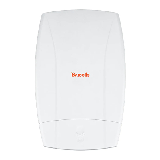
2.2. Dimensions The Baicells Atom outdoor low-gain and high-gain models of user equipment are powerful, standards-based devices designed to connect seamlessly to any standard LTE eNB operating on the same frequency band. The devices have a small, sleek form factor (Figure 3), yet are ruggedized for the most challenging outdoor environments. -
Page 11: Preparing To Install
Table 3: LEDs LEDs vary by model – not all models will have all of the LEDs listed below. Identity Description Color Status Description Reserved for future use Yellow Steady On Reserved for future use Blinking Reserved. for future use The UE is not connected to the network LTE network status Blue... -
Page 12: Figure 5: Lte Network Architecture
2. Insert the service provider's SIM/USIM card into the card slot (Figure 6). Attention: Never power on the unit while installing or uninstalling the USIM card. Doing so could damage the card and the unit. Figure 7: LTE Network Architecture 3. -
Page 13: Figure 9: Power Adaptor
Atom High-Gain UE: Connect the ground cable to the grounding screw in the ground row (Figure 6). The figure is showing the UE mounted on a pole; mounting is covered in step 8. 7. Plug the power adaptor into an electrical outlet (Figure 12). Pay attention to the power adaptor interface directions noted on the adaptor itself. -
Page 14: Figure 12: Attach Ue
a3) Attach the UE to the bracket, and tighten the screw (Figure 18). Figure 19: Attach UE a4) The UE is now ready for installation at its final outside location. Then, proceed to section 7 Basic Configuration. 10. Wall installation: Low-Gain UE: a1) Slip the bracket off of the Atom unit, and fit it on the wall to mark the drilling locations (Figure 11), The marked locations, drill four 10-mm diameter and 70-mm depth holes. -
Page 15: Installation With Baicells Snap Router
7 Basic Configuration. 2.6. Installation with Baicells SNAP Router To explain the installation, the procedure in Table 3 uses a Baicells Atom OD04L Outdoor Low-Gain CPE as the example. Refer to the CPE user manual on the Baicells website to complete some steps as indicated. -
Page 16: Configuration
NOTE: If either the CPE or the router is not running the correct firmware, the router's LTE signal LED will be OFF. Check for the latest firmware on the Baicells website, or contact Baicells support. The setup is complete and ready to work. To configure features using the CPE GUI, go to the next section. -
Page 17: Status Menu
Figure 23: Login Initially, use the default Username = admin/Password = admin (Figure 21). Once you are in the GUI, you will want to change the password; please refer section 3.9.1 Account. 3.4. Status Menu 3.4.1. Overview After logging in, the GUI opens to the Status > Overview page (Figure 24). This page is a dashboard of key information regarding the CPE. -
Page 18: Figure 22: Status
The Device Info pane displays the product name, software version, serial number, etc. The LTE Status pane shows important operational information, such as the CPE's SIM card status and its IMSI and IMEI numbers, wireless frequency being used, eNB connection status, and current signal strength and quality. Under Throughput Statistics you will see downlink (DL) and uplink (UL) data rates for current throughput (kbps), average rates, peak rates, and total throughput. - Page 19 Figure 28: LAN Status Figure 29: Device List Table 6: Status Field Name Description Connection State Connection status between the CPE and the network – either Checking SIM, Scanning, Registering, Acquiring IP, Connected, or Disconnected Signal Intensity Indicates the strength of the signal between this CPE and the serving eNB, either excellent, good, general, bad, or severe.
- Page 20 which the CPE operates Bandwidth The range of frequencies within the band the CPE may use for wireless communications with an eNB, expressed in MHz CINR The Channel Signal-to-Interference-plus-Noise Ratio reflects the signal strength of the signal received from the two antennas in the eNB, expressed in decibels (dB) NOTE: Additional SINR values are reported when a transmitting device is using more than two antennas.
-
Page 21: Network Menu
3.5. Network Menu 3.5.1. LAN Settings Enter the Network > LAN DHCP Server enable, IP address, subnet mask, DHCP range, lease time, UPNP enable. Figure 30: DHCP Settings DHCP Static Leases settings can set by the host’s MAC address. Figure 31: DHCP Static Leases... -
Page 22: Wan Settings
3.5.2. WAN Settings 3.5.2.1. NAT Mode The CPE will be worked at NAT mode, and all 8 APNs can be configured by Default router/Data/Mgmt/Voip bear types. Figure 32: WAN Settings 3.5.2.2. Router Mode When selected Router mode, the CPE will worked at router mode, it can dynamic update router tables. Figure 33: Router Mode 3.5.2.3. -
Page 23: Bridge Mode
Figure 34: Tunnel Mode 3.5.2.4. Bridge Mode When the CPE worked at Bridge mode, the WAN ports address will bridge to LAN port, and the LAN port will worked at trunk mode. Figure 35: Bridge Mode 3.5.2.5. Mixed Mode Mixed mode can configured every APN with different mode (e.g. Bridge), this is a professional mode. -
Page 24: Static Routes
Figure 36: Mixed Mode 3.5.3. Static Routes Set Static routes of the CPE, it can configure LAN or WAN port routes, Gateway, Destination Network and Route Subnet Mask, in Current Settings, show all activated static routes. Figure 37: Static routes... -
Page 25: Dmz
3.5.4. In technology, the DMZ refers to a firewall between incoming WAN traffic and the LAN to which the CPE is connected. Two basic DMZ methods are (a) using a single firewall, also known as the three-legged model, and (b) using dual firewalls (Figure 36). These architectures can be expanded to create complex architectures depending on the network requirements. -
Page 26: Lte Menu
3.6. LTE Menu 3.6.1. Connection Settings LTE connection settings includes Roaming settings, Default connection settings and Power Scan Option. Figure 41: Connection Settings 3.6.1.1. Roaming setting If set Roam enable, the CPE can access to other PLMN network, else the CPE just can access the network PLMN same with the SIM card. -
Page 27: Edit Apn Profile
The CPE supports 8 APN configurations. At least one APN (TR-069) must be configured when the CPE/eNB connect to the Baicells CloudCore. In the window (Figure 42) you will select the APN number (1-8), enable it, enter an APN Name, select the type of IP addressing (IPv4, IPv6, or IPv4v6), identify if it is the default gateway, and choose which type of protocol will be supported on it. -
Page 28: Cell Selection
Figure 45: PIN Management 3.6.4. Cell selection The Cell selection determines which frequencies the CPE’s routine scan of available frequencies will cover. Scanning is a process of tuning to a specific frequency and measuring the simplest signal quality [e.g., Received Signal Strength Indication (RSSI)]. As part of the cell selection and re-selection process, the CPE performs the scan first and then selects a small number of candidate cells to go through the next step of measuring and evaluating signals to select the best eNB that can serve it. - Page 29 Figure 47: Dedicated EARFCN Figure 48: Cell Lock...
-
Page 30: Sim Lock Settings
Figure 49: PCI Only Lock 3.6.5. SIM Lock Settings This feature may be used to lock the SIM card to the operator's network (Figure 48). Each operator has a unique Public Land Mobile Network (PLMN) number. Locking the SIM prohibits the users from accessing another operator's network. -
Page 31: Security Menu
3.7. Security Menu 3.7.1. IP Filtering When using a firewall server in the local network, invoke this setting to enable or disable the firewall for this CPE (Figure 50). Figure 52: Firewall Basic Settings When enable IP/Port Filtering, then the IP/Port Filter can be set. Figure 53: IP / Port Filtering Settings: (1) IP/Port Filtering Mode: Blacklist, White list... -
Page 32: Mac Filtering
Figure 54: IPv6 Filtering Settings: (1) IPv6 Filtering Mode: Blacklist, White list (2) IPv6 Filtering Log Dropped: enable / disable (3) Destination IP Address: the destination IP Address of the filter (4) Source IP Address: the source IP Address of the filter (5) Protocol: TCP, UDP, TCP/UDP, ICMPv6, ALL (6) Destination Port Range: the range of port (7) Source Port Range: the range of port... -
Page 33: Url Filtering
(3) MAC Address: the filtering MAC address 3.7.4. URL Filtering The Uniform Resource Location Filter (URL Filter) allows you to define a list of URL addresses users are forbidden from accessing. When you enable the filter, a Settings window appears. Enter the specific URL address users cannot access, as shown in Figure 54. -
Page 34: Connect Limit
System Security Profiles, include High, Medium, None and Custom, every profiles will corresponding with a set of System Security Settings. Settings: (1) Remote Web Login: enable / disable (2) Remote Telnet: enable / disable (3) Access Control List: enable / disable (4) Block Port Scan: enable / disable (5) Block Syn Flood: enable / disable (6) SPI Firewall: enable / disable... -
Page 35: Nat Menu
In previous Filter configurations, you can select the schedule index like below figure. Figure 60: Schedule Settings 3.8. NAT Menu 3.8.1. Port Forwarding When NAT mode is enabled as the WAN interface type (section 3.5.2), you can redirect a communication request from one address and port number combination to another. -
Page 36: Port Triggering
Figure 61: Port Forwarding settings Table 7: Port Forwarding Field Name Description WAN Port Range Enter the port number range for the remote device in the format of 1000 to 1500 LAN IP Address Enter the local host IP address. The address must be different from the IP address that is set for the LAN Host Settings parameter, but they must be on the same network segment. -
Page 37: Alg
3.9.1. Account This menu is used to change the login password for the CPE (Figure 62). The password must be 5 to 12 characters. Baicells recommends using a combination of upper- and lower-case letters and numbers. Figure 64: Account 3.9.2. -
Page 38: Ntp
3.9.3. The operator's network may may use up to 4 Network Time Protocol (NTP) servers to provide correct time-of-day to network devices. In the CPE GUI you can refresh the local time display using the SYNC WITH BROWSER button; select the time zone that the CPE is in; and enable NTP client to use the default or specified NTP servers for synchronization (Figure 64). -
Page 39: Tr-069 Certificate
Caution: Do not power off the CPE or disconnect it from the computer during an upgrade. To update (upgrade) the CPE to a different firmware version (Figure 67): 1. Download the image file from the Baicells support website (Baicells > Support > Downloads), and save it to your computer. -
Page 40: Diagnosis
3.9.7. Diagnosis 3.9.7.1. TCPDump Figure 71: TCPDump Settings Settings: (1) PC IP Address (2) PC PORT (3) Interface: ALL, LTE0PDN0 (APN0) 3.9.7.2. Ping Figure 72: Ping Diagnosis Settings Settings: (1) IPv4/IPv6: Select the protocol (2) IP Address/Domain: IP Address or URL (3) Count: number of ping count (4) Fragment: yes or no (5) Packet size: 56~1400 Bytes (non-fragment) -
Page 41: Trace
3.9.7.3. Trace Figure 73: Trace Diagnosis Settings Settings: (1) IPv4/IPv6: Select the protocol (2) IP Address/Domain: IP Address or URL 3.9.7.4. Result Figure 74: Diagnosis results 3.9.8. Backup Settings This feature is used to backup the user settings, from the Web-GUI, you can Import / Export the settings. Figure 75: Backup Settings... -
Page 42: System Log
3.9.9. System Log System log is the debug information of the CPE, when select the Setting, it can Export or Clear Logs. Figure 76: System Log Figure 77: System logs 3.9.10. System Messages Use this Web-GUI, you can Export System Message, Collect real-time system information and transfer system message to PC. -
Page 43: Sas Settings
Figure 79: System Messages 3.9.11. SAS Settings This model can support DP and standalone modes, and all SAS parameters can be configured in Web-GUI,... -
Page 44: Reboot
Reboot after you finish setting. 3.10. Reboot Use the Reboot menu to perform a reboot of the CPE, as shown in Figure 77. It can take several minutes for the reboot to complete. After it reboots, the CPE GUI will display the login screen. Caution: The reboot action will disrupt service. -
Page 45: Appendix: Regulatory Compliance
Appendix: Regulatory Compliance FCC Compliance This device complies with part 15 of the FCC Rules. Operation is subject to the following two conditions: (1) This device may not cause harmful interference, and (2) this device must accept any interference received, including interference that may cause undesired operation. - Page 46 (1) l'appareil ne doit pas produire de brouillage, et (2) l'utilisateur de l'appareil doit accepter tout brouillage radioélectrique subi, même si le brouillage est susceptible d'en compromettre le fonctionnement. The antenna(s) used for this transmitter must be installed to provide a separation distance of at least 40cm from all persons and must not be collocated or operating in conjunction with any other antenna or transmitter, End-Users must be provided with transmitter operation conditions for satisfying RF exposure compliance.
Need help?
Do you have a question about the ATOM OD06 CPE and is the answer not in the manual?
Questions and answers