
Subscribe to Our Youtube Channel
Related Manuals for ECR International C13181VAR


Summary of Contents for ECR International C13181VAR
- Page 1 Installation, Operation and Maintenance MODELS C1318-601VAR — 1.5 THRU 5 TON 13 Seer Split System Air Conditioner 0010577101 REV. 4/06...
- Page 2 ! WARNING These instructions are intended as an aid to qualified, licensed service personnel for proper installation, adjustment and operation of this unit. Read these instructions thoroughly before attempting installation or operation. Failure to follow these instructions may result in improper installation, adjustment, service or maintenance possibly resulting in fire, electrical shock, property damage, personal injury or death.
-
Page 3: Table Of Contents
TABLE OF CONTENT 1.Introduction --------------------------------------------------------------------------------------- 2.Nomenclature for Model Number ------------------------------------------------------------- 3.Specification ------------------------------------------------------------------------------------- 4.Unit Inspection ----------------------------------------------------------------------------------- 5.Equipment Protection From Environment ---------------------------------------------------- 6.Installation ---------------------------------------------------------------------------------------- 6.1. General --------------------------------------------------------------------------------------- 6.2.Unit clearances ------------------------------------------------------------------------------ 6.3.Refrigerant piping --------------------------------------------------------------------------- 6.4.Electrical wiring ----------------------------------------------------------------------------- 7.System Startup ----------------------------------------------------------------------------------- 8.Operation ---------------------------------------------------------------------------------------- 9.Miscellaneous ----------------------------------------------------------------------------------- 9.1.Replacement parts -------------------------------------------------------------------------- 9.2.Troubleshooting guide --------------------------------------------------------------------- 9.3.Wiring diagram -----------------------------------------------------------------------------... -
Page 4: Specification
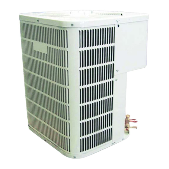
3.SPECIFICATION Figure 1 The dimensions for the condensing unit are illustrated in Figure 1. Physical and electrical specifications are provided in Table 1 for 13 SEER systems respectively. Table 1: Model:C1318-601VAR MODEL: C13181VAR C13241VAR C13301VAR C13361VAR C13421VAR C13481VAR C13601VAR Unit Supply Voltage... -
Page 5: Unit Inspection
4.UNIT INSPECTION This product has been inspected at the factory and released to the transportation agency without known damage. Inspect exterior of carton for evidence of rough handling in shipment. Unpack carefully. If damage is found, report immediately to the transportation agency. 5.EQUIPMENT PROTECTION FROM ENVIRONMENT The metal parts of the unit may be subject to rust or corrosion in adverse environmental conditions. -
Page 6: Unit Clearances
Provide a level concrete slab. To prevent transmission of noise or vibration, slab should not be connected to building structure. Some sort of sound-absorbing material should be placed between the condenser and the slab. A good material to use is rubber and cork pad. For rooftop application, make sure the building construction can support the weight and that proper consideration is given to the weather-tight integrity of the roof. - Page 7 OUTDOOR UNIT ADDITIONAL SUCTION LINE PITCH SUCTION LINE TOWARD OUTDOOR OIL TRAP FOR EACH 20 FOOT UNIT 1/2" FRO EVERY 10' OF LINE RISE OF PIPE INDOOR UNIT ABOVE OR LEVEL TO OUTDOOR UNIT LIQUID LINE MAX. OUTDOOR UNIT SUCTION LINE OIL INDOOR UNIT TRAP WHEN INDOOR INDOOR UNIT...
- Page 8 Refrigerant Line Sizing Check the following table (Table 3) for correct suction and liquid line sizes for any combination of the unit size and the maximum refrigerant line length. Refrigerant Line Length (Ft) 0 - 24 25 - 49 50 - 74 Unit Size Line Outside Diameter (In) (Ton)
- Page 9 1.Tubing should be cut square. Make sure it is round and free of burrs at the connecting ends. Clean the tubing to prevent contamination from entering the system. 2.Make sure that both refrigerant stop valves at the outdoor unit are closed. 3.Push the tubing into the fitting until it stops.
-
Page 10: Electrical Wiring
1.Fully open both shutoff valves. System Superheat 2.Connect service gage manifold to the valve service Ambient Return Air Temperature ( F) ports, being sure to evacuate lines. Temperature At 3.Startup the system (Refer to the Section 7 - "System Condenser Inlet ( F) Startup"). -
Page 11: System Startup
The condensing unit rating plate and the tables of "Physical and Electrical Specifications / Outdoor Units" (Table 1 and 2) provide pertinent data necessary for the selection of proper size electrical service and over-current protection devices. Table 5 provides data on the minimum copper wire size as a function of supply wire length and circuit ampacity. -
Page 12: Operation
8.OPERATION Most single phase units are operated without start relay or start capacitor. Such systems should be off for a minimum of 5 minutes before restarting to allow equalization of pressures. The thermostat should not be moved to cycle unit without waiting 5 minutes. To do so may cause the compressor to stop on an automatic open overload device or blow a fuse. - Page 13 Symptom Possible Cause Remedy Power off or loose electrical connection Make sure main switch is ON. Check and tighten all connections. Incorrect thermostat setting Set thermostat correctly No cooling Defective contactor Check for 24V at contactor coil. Open circuit breaker of blown fuses Reset or replace Defective transformer Check wiring - Replace it.
- Page 14 C1318-601VAR Air Conditioner Wiring Diagram LINE VOLTA GE FACTORY STANDA RD FIELD INSTALLED OPTIONAL ELECTRIC HEATER KIT OPTIONAL LOW VOLT AGE FACTORY STANDA RD FIELD INSTALLED OPTIONAL USE COPPER CONDUCTORS ONLY WARNING CABI NET MUST BE PERMANENTLY GROUNDED AND ALL WIRING TO CONFORM TO I.E.C.,N.E.C.,C.E.C., C.L.C.
- Page 15 Made in P.R.C.
Need help?
Do you have a question about the C13181VAR and is the answer not in the manual?
Questions and answers