Table of Contents
Advertisement
Quick Links
Advertisement
Table of Contents

Related Manuals for MH THYROMAT-BDC


Summary of Contents for MH THYROMAT-BDC
- Page 2 THYROMAT BD DIGITAL CRANE CONTROLLER TABLE OF CONTENTS SECTION PAGE GENERAL 1.1. CONTROL SYSTEM ........................6 1.1.1. Basic System Diagram ......................8 1.1.2. Thyromat Components Identification ..................9 SYSTEM DESIGN 2.1. GENERAL ........................... 10 THYROMAT – BD DIGITAL CRANE CONTROLLER RANGE ........... 10 2.2.
- Page 3 SECTION PAGE 2.15. SELECTION OF ROTOR CONTACTORS .................. 26 2.15.1. Star Connections ........................26 2.15.2. Delta Connections ........................26 2.15.3. V Connections ........................27 2.15.4 W Connections ........................27 2.16. MOTOR THERMAL PROTECTION UNIT ................... 27 2.17. SELECTION OF SPARE PARTS ....................28 PARAMETERS 3.1.
- Page 4 3.4.7. Notch Speed 3 ........................43 SECTION PAGE 3.4.8. Notch Plugging ........................43 3.4.9. Notch Plugging V ........................43 3.4.10. Neutral Plugging V ......................... 44 3.4.11. Neutral Deceleration Profile ....................44 3.4.12. Brake Plugging Volts ......................44 3.4.13. Brakes on Speed ........................45 3.4.14.
- Page 5 4.2.3. Tools and Special Equipment ....................55 SECTION PAGE 4.2.4. Mounting Arrangements ......................56 4.2.5. Mounting Procedure ....................... 58 4.3. ELECTRICAL INSTALLATION ....................59 4.3.1. General ........................... 59 4.3.2. Electrical Connection Instructions ..................60 4.3.3. Tools and Special Equipment ....................64 4.4.
- Page 6 SECTION PAGE 6.8. POSSIBLE CAUSES OF FAILURE..................... 85 6.8.1. Rotor Feedback ........................86 6.8.2. Current Unbalance ......................... 87 6.8.3. Loss of Phase ......................... 88 6.8.4. Current Feedback ........................88 6.8.5. Stack Temp ..........................89 6.8.6. Overload Trip .......................... 89 6.8.7. Over Current ........................... 89 6.8.8.
- Page 7 LATEST REVISIONS ON SUMMARY DOCUMENT Please note the following changes made to Thyromat BDC Digital Crane Controller User Manual: Note: Please be aware that small or minor layout, grammatical, or format changes are not recorded. THYROMAT BDC USER MANUAL REV 8.5 to REV 8.6 CHANGES Section Page Item...
- Page 8 Page numbering has been changed due to revision changes – Section 6 now begins at page 69 through page 87. THYROMAT BDC USER MANUAL REV 8.2 to REV 8.3 CHANGES Section Page Item From Increment Minumum 10 A Minimum 2 A 3.2.2 Minumum 10 A Minimum 2 A...
- Page 9 Section Page Item From Function 3 STATUS MONITORING PAGE MOTOR 3 PHASE CURRENTS MONITORING PAGE This….are also displayed. Remarks 3 Add: To return to status monitoring page, press the Menu key. Add: picture of Menu key … have been rectified. Add: Also clears the fault history when Function in fault history page.
- Page 10 THYROMAT BDC USER MANUAL REV 8 to REV 8.1 CHANGES Section Page Item From 3.2.7 After, applies the mechanical Caution Inserted. brake. 3.2.7 Set the voltage level Set the ceiling voltage level 3.2.7 Torque applied Maximum torque applied 6.8.13 Possible causes: Possible causes: ‘failure’...
- Page 11 THYROMAT BDC SHORT USER MANUAL REV 1 to REV 2 CHANGES Section Page Item From 220 (last line) B 220 Volts control voltage Delete sentence and add “This feature Table 4 Motor overload protection: is not yet implemented” class... Version 9_00 Version 10_00 3.2.17 terminal 4...
-
Page 12: Section 1 : General
THYROMAT digital crane control delivers leading thyristor control technology to a new generation of crane drives. It is the natural successor to MH Automation’s very successful THYROMAT analogue crane drive. Solid state electronics allows a compact design with enhanced reliability. Self-monitoring further improves system safety and reliability. - Page 13 SPECIAL FEATURES FEATURE ADVANTAGES Excellent control Load independent control Excellent repeatable placing of end load Safer working environment for personnel Smooth steady control Safe efficient load handling Gearbox and couplings not subjected to excessive stress Reduced current peaks ...
- Page 14 1.1.1. Basic System Diagram The system’s simplicity is illustrated in the Basic System Diagram (refer to Figure 1-1). This diagram is applicable to both hoist and travel operations. Figure 1-1 : Basic System Operational Diagram SECTION 1 : GENERAL Revision 8.6...
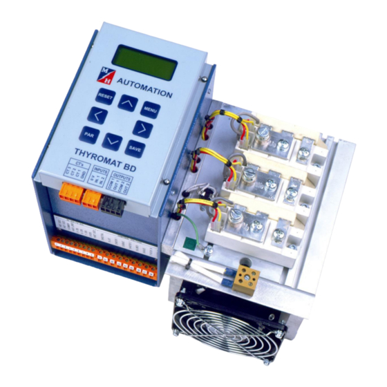
- Page 15 1.1.2. THYROMAT Components Identification The following illustration details the components identification (refer to Figure 1-2). This diagram is applicable to both hoist and travel motions. Figure 1-2 : THYROMAT Components Control box Control connectors on control panel Control panel 10. Thyristor stack Keypad 11.
-
Page 16: Section 2 : System Design
SECTION 2 : SYSTEM DESIGN 2.1. GENERAL The following paragraphs detail the selection of the Thyromat and associated equipment as well as the details for the operation of the THYROMAT. 2.2. THYROMAT BD DIGITAL CRANE CONTROLLER RANGE Table 2-1 details the THYROMAT range. Table 2-1 : THYROMAT Range THYROMAT Ampere Rating... - Page 17 The product range is defined as detailed in Table 2-2. Table 2-2 : Product Range Definition Series Supply Control Current Explanation Voltage Voltage Type Motion Alternating current (ac) applications BD - Digital applications Hoist applications Travel applications 025 A 200 A 1 000 A 030 A 350 A...
- Page 18 2.3. PROTECTION Table 2-3 lists the protection specifications for the THYROMAT. Table 2-3 : THYROMAT Protection Item Specification Control enclosure IP51 Thyristor stack IP00 2.4. THYROMAT - BD DIGITAL CRANE CONTROLLER SELECTION The selection of the THYROMAT for specific mechanical power requirements depends on the base stator current rating on of the slip-ring motor to be used.
- Page 19 Applications Power station cranes. Light workshop cranes. Light stores duty cranes. Light general load handling cranes 2.4.2 Severe Duty (Based on 40% of nominal load permanently on hook). The following lists the severe duty parameters:- Characteristics ...
-
Page 20: Principle Of Operation
Table 2-4 details the selection of the maximum stator current ratings for both hoist and travel in standard and severe duty applications of the various THYROMAT units. Table 2-4 : Maximum Motor Stator Current Ratings THYROMAT - BD Stator Current Unit Sizes Hoist Travel... - Page 21 Before operation can commence, safety circuits monitor the motor for incorrect phase rotation, severe phase differences or unbalance and low three-phase voltage supply and will only allow operation in the event that all the conditions are correct. Electrical interlocking is provided to make sure that the master controller is returned to the zero position after a power or phase loss after which the system will have to be restarted before operation can commence.
- Page 22 2.5.3. Relay Card This card contains the five relays for switching the external contactors and the power supply for these relays. 2.5.4. Phase Shifter Card This card determines the trigger delay angle for the firing of the thyristors as well as circuitry for disabling the unit in the event of incorrect phase rotation, severe phase imbalance or low supply voltage.
-
Page 23: Control System Specifications
2.6. CONTROL SYSTEM SPECIFICATIONS Table 2-5 details the THYROMAT controller Specifications. Table 2-5 : THYROMAT Controller Specifications TECHNICAL DATA CONTROLLER DATA 380 V – 415 V 3 phase 50 Hz Input voltage U - V – W 525 V - 550 V 3 phase 50 Hz Mains supply to THYROMAT Supply variations +10% - 15%... - Page 24 Operating frequency 50 Hz + 1% Varies with rotor resistors values used, standard max. 2.5 x Tn. Braking torque Units may be designed for greater ratings. Consult MH Automation for further details Control box: max. 40 W Unit power dissipation Thyristor stack: Approximately 3,8 W/A of motor actual running current at 60% C.D.F...
- Page 25 Table 2-6 details the THYROMAT Enclosures. Table 2-6 : THYROMAT Enclosures Enclosure Size and Ventilation Table THYROMAT THYROMAT Total Heat Height Length Width MECHANICAL Current Dissipation of Remarks (mm) (mm) (mm) Sizes Ratings Switchgear 25 A 480 W 1400 M100 30 A 480 W 1400...
- Page 26 Step 2 Calculate the mechanical power (P ) required by the motor. Use values of speed, load and efficiency of the motion. Step 3 Obtain the rotor current (R ) at determined P from motor manufacturers data tables. Step 4 Calculate new R Step 5 Calculate the motors rotor resistance (K...
- Page 27 Table 2-7 : Resistor Values % of K Motion Ohms Hoists, all motions with adequate torque margins 0.36 K Hoists, large motors and motors with low torque margins 0.65 K Travels 0.3 K It is a requirement that a crane has the ability to lift 125% of the nominal load. This factor must be taken into account during commissioning process only.
- Page 28 Table 2-8 : Circuit Breaker Selection Circuit Breaker THYROMAT THYROMAT Mechanical Current Size Ratings Frame Trip Unit 25 A NS 100_ STR 22SE 40A M100 30 A NS 100_ STR 22SE 40A 60 A NS 100_ STR 22SE 100A 100 A NS 100_ STR 22SE 100A M150...
- Page 29 2.10. SELECTION OF INTERPOSING INPUT RELAYS Every Thyromat installation makes use of input signals interposing relays. This is required to ensure that the 10V DC Thyromat input signals are confined to the electrical panel. Such 10V DC remains within the electrical panel environment. External switching of directional as well as speed notch signals may then be supplied by the crane control supply, which will control these interposing relays.
-
Page 30: Selection Of Cables
2.12. SELECTION OF CABLES The following paragraphs detail the selection of power supply and control power cables. 2.12.1. Power Supply Cables The specifications of the mains power supply cables must be calculated according to recognised standards (e.g. BS 7671) and the cable manufacturer’s recommendations. Several factors need to be taken into consideration to ensure selection of the correct power supply cables. - Page 31 2.13.1. Contactor Switching Times The THYROMAT is designed to be able to switch contactors at zero current, parameters are provided to enable the user to set the correct switching times so that, during contactors change over arcing is avoided. It is imperative that the users make themselves familiar with the contactors switching times relevant to the installation.
- Page 32 ‘Delta’ and ‘Star’ configurations and although not as popular, ‘V’ and ‘W’ configurations are sometimes also used. In the interests of promoting reliability, MH Automation has a conservative approach to the selection of the contactors and recommends that the continuous rating of the contactors are used rather than intermediate duty which is used for the intermediate rotor contactors.
- Page 33 2.15.3. V Connections Contactor Ith = Motor Rotor Current Example: Motor Rotor Current = 100 A Contactor selected ≥ 100 A Ith 2.15.4. W Connections Contactor Ith = Motor Rotor current Example: Motor Rotor Current = 100 A Contactor selected ≥ 62.5 A Ith 2.16.
- Page 34 MH Automation maintains a stock holding of recommended spares and is able to extend valuable support for all their products. Refer to Section 7 Paragraph 7.3 for further details with regards to the ordering of spares.
-
Page 35: Section 3 : Parameters Bdc-H
SECTION 3 : PARAMETERS BDC-H 3.1. HOIST APPLICATION PARAMETERS LIST Table 3-1 lists the typical parameter settings for BDC-H Hoist Software Version 11.XX applications. Table 3-1: Hoist Parameter List for BDC-H Applications PARAMETER DESCRIPTION SCALE INCREMENT DEFAULT CT ratio Current transformers ratio 50:1 to 3000:1 50:1A Motor current... - Page 36 3.2. PARAMETER DESCRIPTIONS - HOIST The following paragraphs detail the various hoist parameters. CAUTION IF IT IS NECESSARY TO CHANGE PARAMETERS IT IS RECOMMENDED THAT THIS BE DONE IN A CONSERVATIVE MANNER AND ONLY WITH A FULL UNDERSTANDING OF EACH FUNCTION. 3.2.1.
- Page 37 3.2.2. Motor Current PARAMETER DESCRIPTION SCALE INCREMENT DEFAULT Motor current Motor nominal current < 60% of CT Minimum 2A ratio This parameter sets the motor full load stator current. The value to be used is the stator current related to the mechanical power for the specific duty. CAUTION DO NOT EXCEED THE MOTOR NAMEPLATE VALUE FOR THE APPLICABLE DUTY.
- Page 38 3.2.4. Notch 1 3.2.5. Notch 2 3.2.6. Notch 3 PARAMETER DESCRIPTION SCALE INCREMENT DEFAULT Notch 1 Notch 1 speed 5% - 20% Notch 2 Notch 2 speed 5% - 40% Notch 3 Notch 3 speed 5% - 50% These three parameters set the intermediate slow speeds. CAUTION WHEN SPEEDS IN EXCESS OF 30% ARE SELECTED, SPECIAL ROTOR RESISTANCE...
- Page 39 CAUTION ALWAYS ENSURE THAT THE SERVICE TOP LIMIT SWITCH IS CORRECTLY SET TO ALLOW SUFFICIENT STOPPING CLEARANCE FROM THE SERVICE TOP LIMIT SWITCH TO THE ULTIMATE LIMIT SWITCH. THE WORST CASE SETTING WOULD BE WHEN HOIST PLUGGING IS ACTIVE (=YES) AND THE HOOK IS EMPTY.
- Page 40 3.2.9. Lower plugging V PARAMETER DESCRIPTION SCALE INCREMENT DEFAULT Lower plugging V Lower plugging voltage 50% to 100% The lower plugging voltage parameter sets the maximum ceiling % voltage applied during lowering retardation. In the event that this voltage is not sufficient to retard the motor, after an initial period of 750 ms the ceiling is removed and maximum voltage may be applied.
- Page 41 3.2.12. Stop Delay PARAMETER DESCRIPTION SCALE INCREMENT DEFAULT 300 – 1500 ms Stop delay Torque hold delay at 50 ms 600 ms stop This parameter sets the time for zero speed to be held at stop, to allow sufficient time for the mechanical brake to be fully applied.
- Page 42 3.2.15. Ph Shift On Time PARAMETER DESCRIPTION SCALE INCREMENT DEFAULT 0 – 140 ms Ph Shift On Time Phase shifter on time 20 ms 0 ms delay During contactor change over the control card disables the phase shifter from firing the Thyristors for a settable time to allow the contactors to change over under zero current conditions.
- Page 43 3.2.16. Ph Shift Off Time PARAMETER DESCRIPTION SCALE INCREMENT DEFAULT 60 – 240 ms Ph Shift Off Tim Phase shifter off time 20 ms 100 ms delay This parameter complements parameter 15 above. Case 1: Maximum drop-out time > the maximum close-in time In this case the recommended phase shifter off delay time is based on the maximum drop-out time of the contactor minus parameter 15’s set value.
- Page 44 3.2.17. Separate Directional Signals PARAMETER DESCRIPTION SCALE INCREMENT DEFAULT Sep. dir signals Separate directional Yes or No signals This parameter defines the way the input directions are programmed. Parameter set to “No” Parameter set to “Yes” In the event that this configuration keeps on giving a “j. error” message out, it indicates that the Note: THYROMAT unit Motherboard is not compatible with these parameters and the parameters need to be set to “No”.
- Page 45 3.2.18. Load defaults PARAMETER DESCRIPTION SCALE INCREMENT DEFAULT Load defaults Load factory default Yes or No parameters This parameter returns all the parameters to factory default settings. CAUTION NECESSARY CHANGE PARAMETERS IT IS RECOMMENDED THAT THIS BE DONE IN A CONSERVATIVE MANNER AND ONLY WITH A FULL UNDERSTANDING OF EACH FUNCTION.
-
Page 46: Section 3 : Travel Parameters
3.3. TRAVEL APPLICATION PARAMETERS LIST Table 3-2 lists the typical parameter settings for Travel Software Version CTT01.XX applications. Table 3-2 : Travel Parameter List PARAMETER DESCRIPTION SCALE INCREMENT DEFAULT CT Ratio CT ratio 50:1 to 3000:1 50:1 CT Enable Enable CTs Yes or No Motor Current Motor full load current... - Page 47 Brake Plug Soft Brake Plug Soft Yes or No Load defaults Load Defaults Yes or No NOTE: All Travel Control software versions CTT01.XX must be used with Control Panel software versions 9.XX. PARAMETER DESCRIPTIONS – TRAVEL 3.4. The following paragraphs detail the various travel parameters. 3.4.1.
- Page 48 3.4.3. Motor Current PARAMETER DESCRIPTION SCALE INCREMENT DEFAULT Motor Current Motor full load current < 60% of CT ratio This parameter sets the motor full load stator current (Motor flc). The value to be used is the stator current related to the mechanical power for the specific duty. CAUTION DO NOT EXCEED THE MOTOR NAMEPLATE VALUE FOR THE APPLICABLE DUTY.
- Page 49 5% to 60% These three parameters set the intermediate slow speeds. CAUTION WHERE SPEEDS IN EXCESS OF 30% ARE SELECTED SPECIAL ROTOR RESISTANCE DESIGN MAY BE NECESSARY. CONSULT YOUR LOCAL MH AUTOMATION REPRESENTATIVE FOR ASSISTANCE. 3.4.8 Notch Plugging PARAMETER DESCRIPTION...
- Page 50 80%. If the system requires a Braking voltage higher than 80% it may indicate weakness on other aspects of the motion electrical design which may be solved by a complete analysis of the system by MH Automation engineers. Revision 8.6...
- Page 51 3.4.13. Brakes On Speed PARAMETER DESCRIPTION SCALE INCREMENT DEFAULT Brakes on Speed 2% to 10% This parameter sets the speed at which the Brakes will be applied during Neutral stopping. By taking specific care during the setting of this parameter the User can ensure that the exact time when the brakes make contact with the brake Drum or Pads corresponds with the motor speed reaching its standstill point.
- Page 52 3.4.16. Notch 1; 2 and 3 Acceleration Time PARAMETER DESCRIPTION SCALE INCREMENT DEFAULT N123 Accel Acceleration time 5 sec to 20 sec 1 sec 5 sec between slow speed notches This parameter sets the acceleration time between speed notches and is only applicable for slow speed notches1, 2 and 3.
- Page 53 3.4.19. Notch 4 Accel Delay PARAMETER DESCRIPTION SCALE INCREMENT DEFAULT N4 Delay Notch 4 delay 0 to 5 sec This parameter when set at a value > 0 inserts a time delay for engaging notch 4 “full speed”. This is useful when the operation of the Crane requires the driver to perform short movements of the load.
- Page 54 Note Any other combination will cause a J. error fault, which indicates that either speed steps have been selected without defined directional signal or in the event of this parameter being set as YES two directional inputs have been selected simultaneously 3.4.21.
- Page 55 3.4.23. Soft Brake Plugging PARAMETER DESCRIPTION SCALE INCREMENT DEFAULT Brake Plug Soft Yes or No Brake plugging (or reverse plugging) is automatically activated when the Joystick is moved to the opposite direction to the actual motion direction. The amount of Counter torque to be applied during Brake plugging is determined by parameter 12.
- Page 56 3.5. TORQUE APPLICATION PARAMETERS LIST Table 3-3 lists the typical parameter settings for software version CTT01.xx Torque applications. Table 3-3: Torque Parameter List PARAMETER DESCRIPTION SCALE INCREMENT DEFAULT CT Ratio CT ratio 50:1 to 3000:1 200:1 CT Enable Enable CTs Yes or No Motor Current Motor full load current...
- Page 57 Sep Dir Signals Separate directional signals Yes or No Load defaults Load Factory Defaults Yes or No PARAMETER DESCRIPTIONS – TORQUE 3.6. The following paragraphs detail the various travel parameters. 3.6.1. Current Transformer Ratio PARAMETER DESCRIPTION SCALE INCREMENT DEFAULT CT Ratio CT ratio select 50:1 to 3000:1 50:1...
- Page 58 3.6.3. Motor Current PARAMETER DESCRIPTION SCALE INCREMENT DEFAULT Motor Current Motor full load current 10A to 30 A This parameter sets the motor full load stator current (Motor flc). The value to be used is the stator current related to the mechanical power for the specific duty. CAUTION DO NOT EXCEED THE MOTOR NAMEPLATE VALUE FOR THE APPLICABLE DUTY.
- Page 59 N4 delay complete These four parameters set the speeds. CAUTION WHERE SPEEDS IN EXCESS OF 30% ARE SELECTED SPECIAL ROTOR RESISTANCE DESIGN MAY BE NECESSARY. CONSULT YOUR LOCAL MH AUTOMATION REPRESENTATIVE FOR ASSISTANCE. 3.6.9. Notch 1 Plug 3.6.10. Notch 2 Plug 3.6.11.
-
Page 60: Section 4 : Installation
SECTION 4 : INSTALLATION 4.1. GENERAL INSTALLATION The THYROMAT is a complete bolt-on unit keeping the installation simple. The control unit is encapsulated in a dust proof enclosure which is mounted to the thyristor stack. Similarly the thyristor stack is a bolt on unit and is also secured to the equipment (differences in the mounting arrangement of the thyristor stack depend on the model to be used). - Page 61 Excessive vibrations can be caused by various factors such as machine operation and / or reversing contactors etc. In order to minimise the vibration, which contributes to the mechanical wear in the THYROMAT it is suggested that the unit should be mounted close to the edge of the designated mounting panel The THYROMAT must be mounted to a vertical surface with the cooling fins on the thyristor stack aligned in the vertical direction.
- Page 62 4.2.4 Mounting Arrangements Table 4-2 lists the mechanical mounting arrangement for the various THYROMAT controllers. Table 4-2 : Mechanical Mounting Arrangements of THYROMAT - BD Digital Crane Controllers MECHANICAL MOUNTING HOLE ARRANGEMENT (measurement in mm) SIZE M100 M150 Revision 8.6 SECTION 4 : INSTALLATION...
- Page 63 MECHANICAL MOUNTING HOLE ARRANGEMENT (measurement in mm) SIZE M350 200 – 300A Thyromat M500 400A Thyromat M1000 500 – 1000A Thyromat Revision 8.6 SECTION 4 : INSTALLATION...
- Page 64 MECHANICAL MOUNTING HOLE ARRANGEMENT (measurement in mm) SIZE M2000 1200 – 2000A Thyromat 4.2.5. Mounting Procedure Identify a suitable mounting surface. Clean the mounting surfaces and make sure that they are free of any oil or grease. Mark the mounting holes in accordance with the applicable instructions and dimensions identified in paragraphs 4.2.2.
-
Page 65: Electrical Installation
Table 4-3 Mounting Fastener Torque Values MECHANICAL SCREW BOLT SIZE 8 mm 10 mm M100 7 Nm M150 7 Nm M350 15 Nm M500 15 Nm M1000 15 Nm M2000 15 Nm ELECTRICAL INSTALLATION 4.3.1. General WARNINGS 1. DO ATTEMPT MAKE CONNECTIONS TO THE THYROMAT WHILE IT IS CONNECTED TO THE MAINS POWER... - Page 66 CAUTIONS 1. DO NOT MAKE ANY VOLTAGE WITHSTAND TESTS ON ANY PART OF THE THYROMAT - BD DIGITAL CRANE CONTROLLER. 2. DO NOT TOUCH ANY OF THE COMPONENTS ON THE CIRCUIT BOARDS, THEY ARE VOLTAGE SENSITIVE DAMAGED / DESTROYED. 3. MAKE SURE THAT THERE ARE NO POWER FACTOR CORRECTION CAPACITORS...
- Page 67 Figure 4-2 : Electrical Mounting of The THYROMAT Controller Check that the integrity of the earth between the THYROMAT and mounting surface is good (the measured resistance should be 0 ohms). In the event that the earth does not conform, make sure that the THYROMAT mountings to the mounting surface are stripped clean of paint and other contamination ...
- Page 68 Current THYROMAT Mechanical Size Connector / Lug Detail Rating M100 M150 M350 M500 M1000 M2000 25 A 4 x 6 30 A 6 x 6 60 A 16 x 6 100 A 25 x 8 150 A 35 x 8 200 A 70 x 8 350 A...
- Page 69 Current THYROMAT Mechanical Size Connector / Lug Detail Rating M100 M150 M350 M500 M1000 M2000 25 A 30 A 60 A 100 A 150 A 200 A TORQUE 350 A VALUES IN 400 A 500 A 700 A 1 000 A 1 200 A 1 500 A 2 000 A...
-
Page 70: Installation Diagrams
4.3.3. Tools and Special Equipment Table 4-5 lists the Tools and Special Equipment (Electrical) needed to connect the electrical functions of the THYROMAT. Table 4-5 : Tools and Special Equipment (Electrical) THYROMAT - BD Digital Crane Controller Mechanical Size TOOLS / EQUIPMENT M100 M150 M350... - Page 71 Digital Inputs – Main Board 4.4.1. Figure 4-3 illustrates the installation diagram for the digital inputs to the main board. .K02 .K01 .K03 .K04 .K05 Figure 4-3 : Digital Inputs for the Main Board Hoist Applications. .K01 - Hoisting command and first speed step selection. .K02 - Lowering command and first speed step selection.
- Page 72 Digital Inputs – Connectors on the Control Panel 4.4.2. Figure 4-4 illustrates the installation diagram for the digital inputs to the control board. NOT USED IN CRANE APPLICATIONS Figure 4-4 : Digital Inputs for the Connectors on the Control Panel .K11 - Not used in standard hoist and travel applications.
- Page 73 Travel Applications. .KM1 Reverse contactor. .KM2 Forward contactor. .KM7 Brake contactor. .KM41 - Only required in special applications. .KM42 - Only required in special applications. Triac Outputs – Control Panel Board 4.4.4. Figure 4-6 illustrates the installation diagram for the triac outputs from the control board. TRIAC RATINGS –...
- Page 74 4.4.5. Motor Current Inputs Figure 4-7 illustrates the installation diagram for the motor current inputs. Blue Yellow Green Current converter module OA1800 Figure 4-7 : Motor Current Inputs Hoist Applications. CTs always required. Travel Applications. CTs optional. Revision 8.6 SECTION 4 : INSTALLATION...
-
Page 75: Section 5 : Commissioning
SECTION 5 : COMMISSIONING GENERAL Commissioning of the THYROMAT is simplified by default parameters displayed on the control panel (e.g. the operating functions during the functional testing phase of the commissioning process). Equipment configuration and operational adjustments in the event of unique applications are finalised when commissioning the equipment. -
Page 76: Commissioning Procedures
Step 3 Ensure that the rotor resistances are wired correctly, MH Automation always provides the correct values of the resistance steps on the respective rotor schematic diagram. Follow these correctly to ensure that motor performance is correct from the start. - Page 77 Step 7 Powering up of the Thyromat drive:- After ensuring that there are no "earth faults" or "short circuits", the motion’s main circuit breaker (c.b.) may be switched ON. The Thyromat drive will display a power up page, which indicates the type of motion and the version group of its software program. In the event of this page remaining on the display, with periodic reset followed by the same displaying of this page, an Input supply phases has occurred, which does not allow the Thyromat unit to carry further testing prior to the “Health Status”...
- Page 78 Consult MH Automation for advice in the event that the results are out of acceptable boundaries. Step 10 Perform locked Rotor test (Closed rotor circuit) (this test should only be performed if the test mentioned in Step 8 is successful).
- Page 79 It is not possible to elaborate on the causes of the problem due to an immense variety of causes which may influence the results obtained during the tests. It would be advisable to get in contact with the Technical department at MH Automation or any of their accredited representatives or agents for further assistance.
-
Page 80: General Note
Step 14 (Hoist only) Test under load conditions: Run the motion in both directions notch by notch. Specifically look out for the operation of the brake drum. During Hoisting operation, the brake drum must not turn in reverse (lowering direction); if this happens it may indicate one of the following: ... -
Page 81: Hoist Operation
5.4. HOIST OPERATION The following paragraphs detail the operational procedures during hoisting operations; 5.4.1. Hoisting As soon as one of the four hoisting speeds on the master controller is selected, the THYROMAT will activate the hoist contactors which will supply voltage to the motor, a short time delay is provided before the brake is released. - Page 82 released and the lower contactors are activated. The motor is then driven in the lowering direction until the selected speed is achieved. If the load should become an overhauling load then the system will automatically revert to the counter torque mode. This operating principle is selected for safety reasons as the hoist contactors are always activated first.
-
Page 83: Section 6 : Operation Of Control Panel
SECTION 6 : OPERATION OF CONTROL PANEL 6.1. GENERAL The control panel of the THYROMAT controller consists of a liquid crystal display (LCD) and an eight push-button keypad. Figure 6-1 illustrates the display and keypad making up the complete panel. The display has back lighting to aid the identification of the displayed data under darkened conditions. - Page 84 Table 6-1 : Menu Display Pages FUNCTION LINE DESCRIPTION REMARKS Power up display page MH AUTOMATION This page is displayed for 2 seconds after power up. This page displays the type of control and software version POWER UP PAGE This page shows all the alphabetic number.
-
Page 85: Key Pad Push Buttons
Note: If parameter settings are changed and saved while the crane is running (out of neutral with the brake off), these changes only become active once the crane stops running (in neutral with the brake on). 6.2.2. Set Time This function allows the operator to view the current time and date, and also to set the time and date. In the event that the clock is adjusted, the real time clock will only activate once the “SAVE”... -
Page 86: Control Panel Operation
6.4. CONTROL PANEL OPERATION Navigating through the Display, by using the Keypad, is logical and structured as detailed in figure 6-3 Menu Navigation Chart below. Figure 6-3 : Menu Navigation Chart Revision 8.6 SECTION 6 : OPERATION OF CONTROL PANEL... - Page 87 6.5. PARAMETER LISTS PAGE 6.5.1. Accessing the Parameters Page Table 6-3 details the parameters page navigation. Table 6-3 : Parameters Page Navigation STEP ACTION DISPLAY Press the “PAR” key Enter the password * * * * Press “SAVE” key to enter the parameters list Scroll through the parameters with <...
-
Page 88: Set Time Page
6.6. SET TIME PAGE The SET TIME page is illustrated in Figure 6-4. Figure 6-4 : Set Time Page The SET TIME page displays the hour, minute, day, month and year. The cursor indicates the field which can be adjusted. Table 6-4 lists the field name and the range. -
Page 89: Fault History
6.7. FAULT HISTORY The THYROMAT stores a maximum of 254 faults in the order they appear and can be viewed by scrolling through the fault history pages. The faults are listed in the order 01 (most recent fault) to 254(the oldest fault). - Page 90 Table 6-5 : Hoist and Travel Faults AUTOMATIC FAULT RESET IN MEASURED REFER NEUTRAL Rotor feedback No rotor feedback from the Slip-ring Motor. 6.8.1. Current unbal 1 Unbalanced current from current transformer 6.8.2 (a) input 1 Current unbal 2 Unbalanced current from current transformer 6.8.2 (b) input 2 Current unbal 3...
- Page 91 RFB & CURRT LOSS S Simultaneous loss of rotor feedback and 6.8.14 (a) current feedback the letter S indicates that the fault occurred at start before the brakes were released. RFB & CURRT LOSS R Simultaneous loss of rotor feedback and 6.8.14 (b) current feedback, during operations (after the brakes were released.
- Page 92 It is always far more productive for the user to become more familiar with the THYROMAT basic methods of motor control. It is possible to acquire the information from this manual as well as from specific THYROMAT course offered at our head office as well as at certain support centres. The following paragraphs list some possible causes of failures and the effects it may have on the operating system.
- Page 93 system, if the fault persists, the problem may be related to the control box mother board, in this case it is advisable to replace the THYROMAT unit, and send the faulty one to our nearest repair centre. 6.8.2 Current Unbalance Current Unbalance fault indicates that at least one of the stator phase current readings is smaller than 50% of the highest phase current reading.
- Page 94 wires around and check if the unbalance current follows the wire change or remains at its original place. Remaining at the same phase indicates that the fault is in the Control Card and this card needs to be replaced. 6.8.3 Loss of phase A loss of phase fault indicates that a stator phase current was at 0 Amps while the system was running.
- Page 95 Faulty motor stator windings (open circuit on all 3 phases). Faulty Thyristor stack. None of the Thyristors is conducting this is more likely to be caused by a faulty phase shifter card. 6.8.5. Stack Temp The Thyristor stack temperature exceeds 95 Possible causes ...
-
Page 96: Very Important
Rotor contactors are closed all the time, at start the motor starts with very small percentage of rotor resistances, which causes sudden high currents. Mechanical failure 6.8.8 H Loss of Torque (Hoist loss of torque) Applicable to Hoist application only A loss of torque occurred during hoisting and the motor is actually turning in the lowering direction due to the pull caused by the load. - Page 97 6.8.10 Motor Stall Motor is not turning when a running command has been given for a period greater than approximately 10 seconds. Possible causes Mechanical components have seized making it impossible for the motor to turn. Mechanical brake does not release. ...
- Page 98 6.8.13 Joystick error A joystick error occurs if 2 or 4 speeds are requested and the first notch (direction selection) is not present. When the parameter “Sep. dir. Signals” is set as “True” this fault may also indicate that both directions are requested simultaneously.
- Page 99 6.8.15 Not in Neutral Master controller (joystick) wasn’t in the neutral position during powering up of the THYROMAT unit. Returning to the neutral position will reset the condition. NOTE This fault is indicated in the display bottom line as “Not in Neutral”, but it will not be registered on the fault history.
- Page 100 Check that all currents read 0 Amps If this is the case, then insert the C.T.’s plug once again and check if the display remains reading 0 Amps. By following this procedure it is possible to identify which is the part of the current measurement circuit which is faulty, proceed to replace the faulty part.
- Page 101 In any of the tests carried out by the system fails, the corresponding fault is displayed, while the brakes remain closed, the only condition which causes a “brake release” fault to be displayed is if the stator currents measured during this phase are below the value determined by the parameter “Brake Release I”, which sets the required current to release the brakes in % of motor nominal current.
-
Page 102: Section 7 : Maintenance
SECTION 7 : MAINTENANCE 7.1. GENERAL Digital technology is a reliable alternative to analogue systems and it usually does not require maintenance intense tasks. The reliability of the Digital Thyromat Controller ensures that preventative and corrective maintenance is minimal. Maintenance is simplified and equipment down times greatly reduced due to the modular design of the THYROMAT. -
Page 103: Spare Parts List
7.2.2 Ultimate Limit Switch CAUTION ALWAYS CHECK ULTIMATE LIMIT SWITCH CORRECT OPERATION ACCORDING RELEVANT REGULATIONS. It is important that the ultimate limit switch operates to within the tolerances specified by the applicable regulations. 7.3. SPARE PARTS LIST Mechanical Category Code Description Model size... - Page 104 Mechanical Category Code Description Model size Thyristors SKKT106 Thyristor semi-pack M100 to BD SKKT162 Thyristor semi-pack M150 to BD SKKT162 Thyristor semi-pack M350 SKKT250 Thyristor semi-pack M350 SKKT340 Thyristor disk M500 SKKT1200 Thyristor disk M1000 to BD 1000 N980 Thyristor disk M2000 1200 to BD...
- Page 105 525400/ARM Thyristor Phase Arm 400A 525V 525500/ARM Thyristor Phase Arm 500A 525V 525700/ARM Thyristor Phase Arm 700A 525V 5251000/ARM Thyristor Phase Arm 1000A 525V 5251200/ARM Thyristor Phase Arm 1200A 525V 5251500/ARM Thyristor Phase Arm 1500A 525V 5252000/ARM Thyristor Phase Arm 2000A 525V Revision 8.6 SECTION 7: MAINTENANCE...
-
Page 106: Section 8 : Shipping And Storage
SECTION 8 : SHIPPING AND STORAGE 8.1. GENERAL The THYROMAT is simplistic in design and does not require any specialised packing, crates or procedures. When shipping or storing the system in high humidity conditions it is advisable to include a silicone gel sachet in the packaging to absorb any excess humidity. -
Page 107: Section 9 : Acronyms And Abbreviations
SECTION 9 : ACRONYMS AND ABBREVIATIONS 9.1. GENERAL The following list acronyms and abbreviations used throughout this manual. % ....... Percent °C ......Degrees Celsius A ........ Amperes ac ......Alternating Current Acc ......Acceleration C.D.F......Cyclic Duration Factor CPU ......Central Processing Unit CT ......
Need help?
Do you have a question about the THYROMAT-BDC and is the answer not in the manual?
Questions and answers