Advertisement
Quick Links
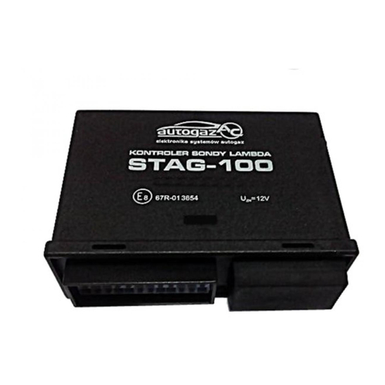
STAG-50, STAG-100, STAG-150
LAMBDA SENSOR CONTROLLER
INSTALLATION & PROGRAMMING MANUAL
version : V1.77 -V1.79
Manufacturer:
AC Spółka Akcyjna.
15-181 Białystok, ul. 42 Pułku Piechoty 50, Poland
tel. +48 85 7438148, fax +48 85 653 8649
www.ac.com.pl, e-mail:
autogaz@ac.com.pl
Page 1 of 17
Advertisement

Summary of Contents for autogaz AC STAG-50
- Page 1 STAG-50, STAG-100, STAG-150 LAMBDA SENSOR CONTROLLER INSTALLATION & PROGRAMMING MANUAL version : V1.77 -V1.79 Manufacturer: AC Spółka Akcyjna. 15-181 Białystok, ul. 42 Pułku Piechoty 50, Poland tel. +48 85 7438148, fax +48 85 653 8649 www.ac.com.pl, e-mail: autogaz@ac.com.pl Page 1 of 17...
-
Page 2: Set Components
After starting of the engine and reaching of required rpm (in the automatic mode green LED blinks) LPG supply is switched on (green LED shines constantly). The LPG output is controlled with a actuator and depends on lambda sensor indications. All STAG-50/100/150 parameters are set with an external tester or a PC (AcLpgWin software). - Page 3 WIRING DIAGRAM AND INSTALLATION MANUAL The STAG-50/100/150 controller should be mounted within the engine room in the place, which is not exposed to high temperature, water and fuel. CAUTION! It is recommended to install the controller vertically using its mounting eye and a screw, placing sockets downward to avoid water penetration.
- Page 4 STAG-50 installation diagram Page 4 of 17...
- Page 5 STAG-100 installation diagram RELAY FUNCTIONS IN STAG-100 Connect Connect wires Cut/Connect ”Relay” parameter resistor Emulation of single- yellow Injector power supply ~20Ω Emulation of injections point injector white-green point Emulation of multi- yellow +12 power supply of ~100Ω Emulation of injections point injector white-green all injectors...
- Page 6 STAG-150 Installation diagram. OUTLETS OF STAG 150 EMULATOR WIRE SET No. WIRE COLOUR DESCRIPTION (option) BLACK FRAME POWER SUPPLY OF EXTERNAL EMULATOR (option) BLUE + 12V POWER SUPPLY OF EXTERNAL EMULATOR YELLOW INJECTOR 1 - POWER SUPPLY YELLOW-BLACK INJECTOR 1 - COMPUTER GREEN INJECTOR 2 - POWER SUPPLY GREEN-BLACK...
- Page 7 STAG-50/100/150 - PROGRAMMING WITH A PC AND AcLpgWin SOFTWARE To set STAG-50/100/150 parameters using a PC it is indispensable to connect the PC through a RS socket and a RS-232 interface to the STAG-50/100/150 programming socket and start the AcLpgWin.exe software.
- Page 8 -control panel - working mode change (mouse click ) - open help file - window layout - open gauges window - controller parameters readout - grid on - start / stop oscilloscope - oscilloscope time base change - save visualisation file - open visualisation file - oscilloscope on / off;...
- Page 9 On the oscilloscope you can see basic STAG controller signals: lambda sensor, lambda simulation, TPS and actuator positions . Below the graph, there is a signal table. You can enable each graph and select its colour in the “Graph” column. Apart from the oscilloscope, signal values are displayed in the “Values”...
- Page 10 STAG-50/100/150 ADJUSTMENT PARAMETERS IGNITION COIL - according to the connection of rpm pulse and ignition type it is indispensable to choose such type of coil to obtain the same rpm indication at the tachometer and software window. In certain vehicles it is indispensable to use an ignition pulse adder.
- Page 11 ADJUSTMENT FROM LAMDBA SENSOR - adjustment from sensor on / off LAMDBA SENSOR THRESHOLD - a voltage causing mixture weakening ACTUATOR SPEED ABOVE TPS THRESHOLD- actuator speed during LPG – air mixture adjustment set by the sensor during idle operation ACTUATOR SPEED BELOW TPS THRESHOLD- actuator speed during LPG –...
- Page 12 LPG LEVEL SENSOR – depending on LPG level sensor, voltage thresholds for activation of relevant LEDs indicating LPG level FAULTS DETECTED BY THE STAG-50/100/150 CONTROLLER VOLTAGE SUPPLY FAULT - to big voltage drop or disconnection of battery, which causes controller's...
- Page 13 CONFIGURATION To match controller parameters to the individual vehicle type choose CONFIGURATION menu; software detects petrol engine parameters and automatically adjusts LPG mode parameters. CONFIGURATION is activated with the key GASOLINE. Dialog windows shows commands to execute to configure the controller for a LPGpowered vehicle. During check of gasoline mode parameters individual parameters will be displayed within a table;...
- Page 14 Finish the gasoline configuration pressing one of following keys: NEXT - LPG mode configuration OK - save gasoline mode settings SKIP - skip settings CONFIGURATION – LPG NOTE: LPG MODE CONFIGURATION SHOULD BE MADE AFTER PRELIMINARY PRESSURE REGULATOR ADJUSTMENT! (SEE QUICK START P. 12) LPG mode configuration may be activated with LPG or NEXT - if gasoline configuration has been performed previously.
- Page 15 Displayed voltage will be quickly responding to changes in float position. VERSION The STAG-50/100/150 controller from the version 1.60 on is provided with the option of user-made software modification. After connecting the controller to a PC the new window VERSION appears.
- Page 16 wait until the installation progress bar reaches 100% when the message “Programming finished successfully” appears, press OK. The controller performs restart and begins to work with the new version of the software. If the programming process is interrupted or there are some errors, diagnostic software will display the “Software error ...”...
-
Page 17: Technical Data
TECHNICAL DATA Operation voltage 12V ( +30% - 25% ) Max current consumption 0,3 A Max current supplied to LPG control system 6,5 A Max injection emulator current Ignition pulse input voltage 3 – 12 V PROGRAMMABLE FUNCTIONS Number of cylinders and ignition type…………………3, 4, 5,6, 8 cylinders, single or double coil Type of throttle position sensor………………………………..0-5 V, 5-0V linear, switch 0-12/12-0 V Lambda sensor type…………………………………..0-1V, 0-5V, 5-0V, 0.8-1.6V, standard or resistive Lambda sensor emulation………………………………………………square wave, disconnected, frame...
Need help?
Do you have a question about the STAG-50 and is the answer not in the manual?
Questions and answers