Advertisement
Quick Links
The User's Guide for the Oxford Asylum Jupiter XR Atomic Force Microscope (AFM) in Tapping Mode
The Shortest Possible Version of this Manual
1. Turn on pump if needed
2. Check in to tool reservation on Lab Resources
3. Log onto Windows
4. Launch Jupiter software
5. Select BlueDrive AC Air Mode from Mode Master panel
6. Load probe
7. Load sample
8. Lower AFM head ~2 mm above sample surface using joystick
9. Focus on tip. Set detector laser. Set BlueDrive Laser. Mark tip location. SET tip focus
10. Focus on sample surface. SET sample focus location
11. Toggle back to tip view, and click "Move to Pre-Engage Height"
12. Tune cantilever for 1V amplitude
13. Click "Start Tip Approach"
14. Set up Master Panel. Input scan size and rate. Set Setpoint to 800 mV. Give file a name and
designate a file path for saving data.
15. Click "Frame Up"/"Frame Down" to start tip raster. Optimize data image.
a. Lower and tune setpoint, until image shows up in Height data window
b. Increase Gain until trace/retrace have good overlap and no ringing
16. To collect an optimized image "Frame Up"/"Frame Down" to start a new frame with optimized
data
17. Done?
a. Click stop
b. Click Remove Sample
c. Open AFM hood and remove sample.
d. Optional: remove and reclaim the tip
e. Turn off pump
f.
Log out of Windows.
g. Fill out log book
1
Advertisement

Summary of Contents for Oxford Asylum Jupiter XR
- Page 1 The User’s Guide for the Oxford Asylum Jupiter XR Atomic Force Microscope (AFM) in Tapping Mode The Shortest Possible Version of this Manual 1. Turn on pump if needed 2. Check in to tool reservation on Lab Resources 3. Log onto Windows 4.
- Page 2 Table of Contents Introduction and Hardware Overview…………………………………………………………………………………………..pg 3 Before You Get Started…………………………………………………………………………………………………………………pg 6 Performing Tapping Mode AFM……………………………………………………………………………………………………pg 6 Saving data as an image, and image processing……………………………………………………………………………pg 18 Changing the AFM Probe……………………………………………………………………………………………………………..pg 21...
- Page 3 AFM in tapping mode microscopy. A note for users of the previous tool: There are some ways that this Oxford Asylum Research tool differs from the previous Veeco Dimension V tool. Notably, the old tool achieved the tapping frequency by oscillating the tip with piezo electric elements in the AFM tip holder.
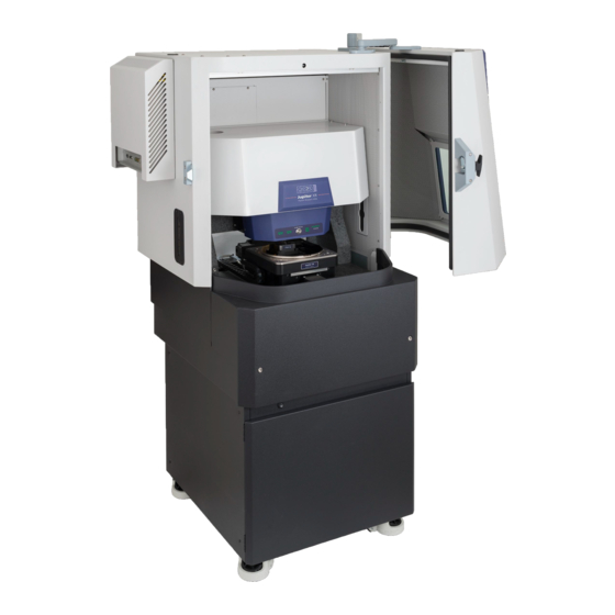
- Page 4 Inside the shielding, the sample stage is housed inside the tool. The stage is mounted on a granite slab that is supported by an air table in order to reduce noise. The sample stage clamps samples in place during scans. Samples are clamped in place by a vacuum or by magnets that are embedded in the stage (Fig 2b).
- Page 5 Figure 3. Images of external components. This includes (a) the “backpack” on the left-hand side of the AFM hood, indicated with a red arrow. Image (b) includes, from top to bottom, the stage controller, the AFM controller, and the black UPS box. Image (c) shows the CPU, indicated by a blue arrow, and the sample stage pump, indicated by a purple arrow.
-
Page 6: Before You Get Started
Before you get started You need an account on the UTD Cleanroom Scheduler, Lab Resources. This system is the scheduler for time on the tool, and manages billing for tool usage. AFM tips are also available for purchase through the scheduler as an accessory, although staff need to be notified when they need to supply the tip. - Page 7 Figure 5. Launching the Jupiter software (a) from the icon indicated by the orange square. When the software launches (b), wait for the “Ready” message and check marks, indicated by the green rectangle. In the Standard tab of the Mode Master panel, select BlueDrive AC Air Topography Configure screen.
- Page 8 Figure 6. Images of a dual screen configuration. In (a), an image of the left-hand screen is shown with 4 numbered panels; these panels are the Master panel, the Engage panel, the Sum and Deflection panel, and the Video panel. In (b), an image of the right-hand screen is shown with 5 numbered panels, including the Height Retrace, Phase Retrace, Z Sensor Retrace, Amplitude Retrace, and the Master Channel panel.
- Page 9 Load probe. On the Engage panel, click on “Change Cantilever” (Fig 7). Wait for this button to turn green. On the AFM head, the “Ok to Remove” light will come on. At this point, reach into the AFM and grab the green lever to the right of the z-scanner. Push the lever down to disengage, and push it back. At the end of the travel path, a magnet locks the lever in place.
- Page 10 Figure 8 (a) using the Allen key to remove screw from the sample stage to access the vacuum clamping force. In (b), please note that there is a sample box in the tool. The Allen key should be kept here, along with any screws that are temporarily removed for a user’s work.
- Page 11 the focus down to visualize the tip in the Video panel. As focus changes, the user may adjust illumination intensity in the video panel (Fig 9b); using the mouse, left click on the “I” slider at the bottom of the video panel and drag to the left or right.
- Page 12 Figure 9. Images of the (a) Engage panel and (b) the Video panel that are useful for locating the tip and the sample surface. In the Video panel (b), the crosshair for moving the red detector laser are circled in red;...
- Page 13 Focus on sample surface. For some samples, this may be as easy as bringing the focus down beyond the tip using the same down arrows in the Engage panel that were used to locate the tip. In the Engage panel (Fig 9a), there are 2 values called “Focus Position” and “Tip Position.” The user can bring the focus position down below the tip position by about 1 mm.
- Page 14 Figure 11. The cantilever tune window has no data when initially opened. Verify the Target Amplitude, indicated by the red circle is set to 1.00 V. The GetReal button indicated by the green square opens a menu of commonly used AFM probes. Figure 12.
- Page 15 Figure 13. The Cantilever tune window after clicking Auto Tune, indicated by the red arrow. The computer calculates the resonance frequency of the cantilever (black trace) Figure 14. An image of the Master Panel...
- Page 16 In the Engage panel, click on “Start Tip Approach.” The user will now fill in some values in the Master panel before collecting data (Fig 14) The Master panel is divided into a few grey sections with parameters that will be adjusted and set by the user before the scan starts.
- Page 17 When a frame is complete and the user is satisfied with data collection, click on “Stop” in the Master panel. This ends data collection and tip raster. In the Engage panel, on “Change Sample”. This raises the AFM head far above the sample stage, and moves the sample stage out of the tool toward the user.
-
Page 18: Saving Data As An Image, And Image Processing
Saving data as an image, and image processing Data is saved in an .ibw (Igor binary wave) file extension. This data formate is not an image or surface measurement file. The user will use some software, either the Asylum program on the tool or image processing software such as Gwiddeon, to manipulate the .ibw file to obtain useful data. - Page 19 Figure 15. An image of the Save Graphics File window that allows the user to export data as an image Figure 16. An image of the Modify panel (a), in which the user may “ultra restore” data back to the raw format.
- Page 20 To save data as an image (flattened or not), the user will open the main File menu in the software, and click on “Save Graphics”. This opens a Save Graphics File window (Fig 15), where the user can define the size of the image, choose the file extension from a drop down menu (including JPEG and TIFF), and indicate a file name and path.
-
Page 21: Changing The Afm Probe
Changing the AFM Probe The user will want to learn how to change the AFM probe (aka “tip” or “cantilever”) for many reasons: to install a new probe at the beginning of the user’s session, to replace a probe that is broken or dull in the middle of a user’s session, or to install different tips that allow the user to access multiple modes of AFM during a session. - Page 22 Disengage the green lever that locks the z-scanner in place (Fig 19a). Using a thumb and a forefinger, use one hand to carefully grasp the z-scanner on either side and pull it out of the tool (Fig 19b) Figure 19. Images of (a) the user disengaging the green lever on the AFM head and (b) the correct technique for grasping and removing the z-scanner Carefully, carry the z-scanner over to the stereoscope, and place it on the table.
- Page 23 Figure 20. Images of steps to remove the old probe, including (a) using the Phillips head screwdriver to loosen the central screw and (b) viewing the z-scanner under the stereoscope in bay 5. Place the z-scanner under the stereoscope (Fig 20b). Turn on the stereoscope light, and adjust and focus the stereoscope until the probe is visible in the eyepieces.
- Page 24 Figure 21. Image of a cantilever in the tip holder. Notice the channel created by the two square pillars and the back wall, indicated by red arrows. An image of (b), a sharp, fresh tip as viewed at high magnification under the stereoscope. Using the tweezers, grasp the old probe by the sides, and pull it out of the channel.
Need help?
Do you have a question about the Asylum Jupiter XR and is the answer not in the manual?
Questions and answers