Table of Contents
Advertisement
Quick Links
Air Monitor Corporation
116-044-91.P65 (8/31/10)
Installation, Operation,
and Maintenance Manual
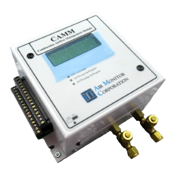
CAMM
Microprocessor Based
Combustion Air ow Management Module
Versions 5.3X
Installation, Operation & Maintenance
Air Monitor Corporation provides complete
technical support between the hours of
7 a.m. and 5 p.m. PST, M-F
Contact our Service Department
Toll Free: 1-800-AIRFLOW
or fax us at 1-707-526-2825
CAMM - IO&M Manual
Advertisement
Table of Contents

Summary of Contents for Air Monitor CAMM
- Page 1 CAMM Microprocessor Based Combustion Air ow Management Module Versions 5.3X Installation, Operation & Maintenance Air Monitor Corporation provides complete technical support between the hours of 7 a.m. and 5 p.m. PST, M-F Contact our Service Department Toll Free: 1-800-AIRFLOW or fax us at 1-707-526-2825 Air Monitor Corporation CAMM - IO&M Manual...
-
Page 3: Table Of Contents
SECTION 4 – INSTALLATION RECEIVING AND INSPECTION ..................... 5 LOCATION ............................. 5 MOUNTING ............................ 5 PROCESS CONNECTIONS ......................6 POWER/SIGNAL CONNECTIONS ..................... 7-8 INPUT/OUTPUT SELECTION ......................9 DISPLAY CONTRAST ADJUSTMENT ................... 9 Air Monitor Corporation CAMM - IO&M Manual 116-044-91.P65 (8/31/10) - Page 4 TRANSMITTER OUTPUT CALIBRATION ................55-56 SECTION 7 – MAINTENANCE ......................57 SECTION 8 – TROUBLESHOOTING ....................58-59 SECTION 9 – PARTS LIST ......................60-61 SECTION 10 – CUSTOMER SERVICE ....................62 Air Monitor Corporation CAMM - IO&M Manual 116-044-91.P65 (8/31/10)
-
Page 5: Instrument Warranty
This document contains confidential technical data, including trade secrets and proprietary information which are the sole property of Air Monitor Corporation. The use of said data is solely limited to use as specified herein. Any other use is strictly prohibited without the prior written consent of Air Monitor Corporation. -
Page 6: Section 1 - General Information
1 – GENERAL INFORMATION 1.1 – DESCRIPTION The CAMM is an ultra-low differential pressure "smart" mass flow transmitter designed to convert the low magnitude pressure signals generated by airflow stations or probes, plus process temperature and static pressure inputs into multiple output signals (4-20mA, 0-5VDC or 0-10VDC) linear to mass flow, temperature, and pressure. -
Page 7: Section 2 - Performance Specifications
2.2 – INDICATION 120VAC 19.2VA 18.67VA 106VA 92VA Displays. Graphical backlit LCD provides up to five Circuit Protection. Power input is isolated, fused, and lines of data display. reverse polarity protected. Air Monitor Corporation CAMM - IO&M Manual 116-044-91.P65 (8/31/10) -
Page 8: Section 3 - Features
AUTO-zero On/Off and Interval are available and configurable using the Operator Setup menu. 3.5 – AUTO-purge MANAGEMENT The CAMM provides the capabilities of establishing purge frequency and duration, while also giving the Operator a choice of either internally timed cycle frequency or externally triggered purge initiation. During the purge cycle all transmitter outputs and displays are maintained at their last value prior to the start of the purge cycle. -
Page 9: Special Functions
3.8 – K-FACTOR The CAMM is equipped with a K-factor feature which allows for the introduction of a bias and/or gain factor into the transmitter's flow calculations. The K-factor feature is intended to be used in two types of applications: 1. -
Page 10: Section 4 - Installation
Information Sheet"), and requires no additional calibration/verification prior to installation. 4.2 – LOCATION • The CAMM is housed in a NEMA 1 enclosure which provides some degree of protection which is sufficient for most clean indoor locations. • Where additional protection is deemed necessary, the CAMM should be mounted in an enclosure with adequate NEMA rating. -
Page 11: Process Connections
– Low Port on CAMM connects to Static Pressure from airflow measuring devices. Although any size of tube/pipe can be used, the response time of the CAMM to process change can increase if there is a increase in tube/pipe size or an increase in tube/pipe length. -
Page 12: Power/Signal Connections
4.5 – POWER/SIGNAL CONNECTIONS All power and signal wiring is done at the terminal strip at the left side of the CAMM. Figure 4.3 below represents the terminal strip and the connections for power input and the various inputs/outputs available. - Page 13 Input Power (Terminals 14, 15, and 16). Power required by CAMM must be connected to terminals 15 and 16. Earth ground should be connected to Terminal 14. When powering multiple units from one power source, polarity must be maintained.
-
Page 14: Input/Output Selection
Inputs have a single jumper covering two pins, and outputs have two jumpers covering four pins. 4.7 – DISPLAY CONTRAST ADJUSTMENT To compensate for different ambient lighting conditions and viewing angles, the CAMM display's contrast can be adjusted for optimum visibility. -
Page 15: Section 5 - Operation
The CAMM has been configured and calibrated at the Factory to customer specified parameters which are recorded on the CAMM Factory Setup Information Sheet, included with the unit. Review this information and verify that the CAMM setup is correct for your applications. If any problems or discrepancies are detected, contact Air Monitor's Customer Service Department at 1-800-AIRFLOW prior to proceeding. -
Page 16: Normal Operation
ESC and UP, then scrolling until Perform Auto-Purge is displayed, then press ENT. *Note: The interval clock for AUTO-zero and AUTO-purge cycles is initiated when the CAMM's power switch is turned on. The time intervals (preset in Operator Set-Up menu) will then start their timing sequence. -
Page 17: Configuration
The CAMM's Onboard Microprocessor Controls Configuration: Operating parameter selection; input/output activa- tion and scaling, display scaling, and transducer calibration. The customer can verify configuration and change certain parameters (within defined ranges) by entering the CAMM's Configuration mode. This is accomplished using the four pushbuttons located on the CAMM's top cover. -
Page 18: Pushbutton Definition
*Must be pressed and held before other button(s) are pressed. NOTE Pushbuttons are momentary type and should be quickly pressed and released to initiate desired change, unless otherwise instructed to press and hold. Air Monitor Corporation CAMM - IO&M Manual 116-044-91.P65 (8/31/10) -
Page 19: Configuration Programming
OPERATOR SETUP Pressing ENT again will enter the user into the Main Menu of configuration programming. The display will indicate: Operator Password Selection Refer to next page for Main Menu Selections. Air Monitor Corporation CAMM - IO&M Manual 116-044-91.P65 (8/31/10) - Page 20 Menu Inactivity Timeout Selection Allows for the selection a time after which the unit returns to normal operation if no activity in the Operator Menu. Exit Operator Setup Returns display to Normal operation. Air Monitor Corporation CAMM - IO&M Manual 116-044-91.P65 (8/31/10)
- Page 21 "arrow" symbol displayed and will display Not Installed beneath the selection description. Example: Network Not Installed The remainder of this Section details steps to verify or change Configuration Programming of all Main Menu Selections. Air Monitor Corporation CAMM - IO&M Manual 116-044-91.P65 (8/31/10)
-
Page 22: Operator Password Selection
5. Use UP or DN to select remaining parameters to be changed. 6. Follow Step 4 to make any changes to parameters. 7. To return to Main Menu, select Return to MAIN MENU in Operator Password Selection menu and press ENT. Air Monitor Corporation CAMM - IO&M Manual 116-044-91.P65 (8/31/10) -
Page 23: Transmitter Scaling & Configuration
5.8 – TRANSMITTER SCALING & CONFIGURATION This Main Menu selection is where all application specific data is entered to configure the CAMM for a unique application. Data is entered in sub-menu, Process Configuration, and as applicable, sub-menus, Temperature Configuration and Absolute Pressure Configuration. - Page 24 6 Not available if Square Root is OFF. If Square Root is OFF, Process Type is Differential Pressure (D.P.). 7 Available only if Process Type is Transmitter Flow. Available units depends on Process Type selected. Air Monitor Corporation CAMM - IO&M Manual 116-044-91.P65 (8/31/10)
- Page 25 Display of process is not affected by this selection, and will indicate the actual process value. If optional Analog Output 4 is selected to represent TRANSMITTER, it will act the same as Transmitter Output 1. Air Monitor Corporation CAMM - IO&M Manual 116-044-91.P65 (8/31/10)
- Page 26 T/hr Tons per hour T/day Tons per day gm/s grams per second kg/s kilograms per second kg/m kilograms per minute kg/hr kilograms per hour Percent Air Monitor Corporation CAMM - IO&M Manual 116-044-91.P65 (8/31/10)
- Page 27 1. All units listed are available if Density Compensation is OFF. 2. Only these units are available if Density Compensation is ON and Type is Volumetric. 3. Only these units are available if Density Compensation is ON and Type is Mass. Air Monitor Corporation CAMM - IO&M Manual 116-044-91.P65 (8/31/10)
- Page 28 (–2.5000 to 2.5000) XX.XXX (–25.000 to 25.000) XXX.XX (–250.00 to 250.00) X,XXX.X (–2,500.0 to 2,500.0) XX,XXX (–25,000 to 25,000) XXX,XX0 (–250,000 to 250,000) XXXX,X00 (–2500,000 to 2500,000) XXXX,000 (–9999,000 to 9999,000) Air Monitor Corporation CAMM - IO&M Manual 116-044-91.P65 (8/31/10)
- Page 29 If Density Compensation is ON (see Process Configuration above), display will indicate: Input Linearization Selection If Density Compensation is OFF display will indicate: Temperature Off/On Selection 11. Press ENT and display will indicate current selection of applicable menu from Step 10. Air Monitor Corporation CAMM - IO&M Manual 116-044-91.P65 (8/31/10)
- Page 30 If Density Compensation is OFF (see Process Configuration above), display will indicate: Abs. Pressure Off/On Selection 18. Press ENT and display will indicate current selection of applicable menu from Step 17. Air Monitor Corporation CAMM - IO&M Manual 116-044-91.P65 (8/31/10)
- Page 31 21. Follow Step 19 to make any changes to parameters. 22. To return to the Transmitter Scaling & Configuration menu, select EXIT in the Absolute Pressure Configuration sub-menu and press ENT. Air Monitor Corporation CAMM - IO&M Manual 116-044-91.P65 (8/31/10)
- Page 32 Barometric Pressure Barometric Pressure 20.00 to 32.00 in.Hg 29.92 in.Hg Selection in 0.01 increments Elevation Elevation 0 to 10,000 Feet or 0 Feet Selection 0 to 3,048 Meters Continued on next page Air Monitor Corporation CAMM - IO&M Manual 116-044-91.P65 (8/31/10)
- Page 33 Steps in this Section marked with * indicate values or choices Configuration Menu previously made in Process Congiuration. 11 Available only with Calculate Flow. Return to 12 Depends on selection immediately above. MAIN MENU 13 Available only with Calculate D.P. Air Monitor Corporation CAMM - IO&M Manual 116-044-91.P65 (8/31/10)
- Page 34 32. To return to the Transmitter Scaling & Configuration menu, select EXIT in the Calculator for Max Diff. Pres. or Flow sub-menu and press ENT. 33. To return to the Main Menu, select Return to MAIN MENU in the Transmitter Scaling & Configuration menu and press ENT. Air Monitor Corporation CAMM - IO&M Manual 116-044-91.P65 (8/31/10)
-
Page 35: Low Pass Filter Selection
Main Menu. Note: If user desires not to change the setting and return to Main Menu, press ESC. Unit will remain programmed as it was originally. Air Monitor Corporation CAMM - IO&M Manual 116-044-91.P65 (8/31/10) -
Page 36: Auto-Zero Configuration
5. Use UP or DN to select remaining parameters to be changed. 6. Follow Step 4 to make any changes to parameters. 7. To return to Main Menu, select Return to MAIN MENU in AUTO-zero Configuration menu and press ENT. Air Monitor Corporation CAMM - IO&M Manual 116-044-91.P65 (8/31/10) -
Page 37: Auto-Purge Configuration
5. Use UP or DN to select remaining parameters to be changed. 6. Follow Step 4 to make any changes to parameters. 7. To return to Main Menu, select Return to MAIN MENU in AUTO-purge Configuration menu and press ENT. Air Monitor Corporation CAMM - IO&M Manual 116-044-91.P65 (8/31/10) -
Page 38: Special Function Configuration
0.00 to 100.00% 0.00% in 0.01 increments % Dev Alarm Delay 0.0 to 10.0 Min. 5.0 Min. in 0.1 increments Available only if Process Return to Type is Flow. MAIN MENU Air Monitor Corporation CAMM - IO&M Manual 116-044-91.P65 (8/31/10) - Page 39 5. Use UP or DN to select remaining parameters to be changed. 6. Follow Step 4 to make any changes to parameters. 7. To return to Main Menu, select Return to MAIN MENU in Special Function Configuration menu and press ENT. Air Monitor Corporation CAMM - IO&M Manual 116-044-91.P65 (8/31/10)
-
Page 40: K-Factor Configuration
X.XX% in 0.01 increments Max. Diff. Pressure Value based calculated or X.XXXXX in. WC selected Gain / Bias Return to *Available range depends MAIN MENU on operating span versus natural span. Air Monitor Corporation CAMM - IO&M Manual 116-044-91.P65 (8/31/10) - Page 41 5. Use UP or DN to select remaining parameters to be changed. 6. Follow Step 4 to make any changes to parameters. 7. To return to Main Menu, select Return to MAIN MENU in parameter menu and press ENT. Air Monitor Corporation CAMM - IO&M Manual 116-044-91.P65 (8/31/10)
-
Page 42: Enhanced Display Configuration
1. While in Main Menu, use UP or DN to scroll to: Configuration LINE 1 2. Press ENT to enter Enhanced Display Configuration menu. Display will indicate LINE 1 3. Press ENT to enter Setup menu. Display will indicate: FILTER Air Monitor Corporation CAMM - IO&M Manual 116-044-91.P65 (8/31/10) - Page 43 14. Use UP or DN to scroll to desired filter setting. Press ENT and filter setting will be stored in memory and display will indicate as in Step 12. 15. Press UP and display will indicate: LINE 2 EXIT 16. Press ENT then UP and display will indicate: LINE 3 Air Monitor Corporation CAMM - IO&M Manual 116-044-91.P65 (8/31/10)
- Page 44 ESC + ENT: Exits "Set Custom Text". Does not enter any changes to the display since the last time ENT was pressed. UP + DN: Jumps up five characters at a time, to the desired character. DN + UP: Jumps down five characters at a time, to the desired character. Air Monitor Corporation CAMM - IO&M Manual 116-044-91.P65 (8/31/10)
- Page 45 Transmitter Flow is selected as Process Type. Available only if Percent Deviation has been selected as a Special Function. ASCII Character Chart < " > & ¥ Air Monitor Corporation CAMM - IO&M Manual 116-044-91.P65 (8/31/10)
-
Page 46: Analog Output Configuration
Note: If user desires not to change the setting and return to Analog Output Configuration menu, press ESC. Unit will remain programmed as it was originally. 5. To return to Main Menu, select Return to MAIN MENU in Analog Output Configuration menu and press ENT. Air Monitor Corporation CAMM - IO&M Manual 116-044-91.P65 (8/31/10) -
Page 47: Transducer Span Selection
5. Use UP or DN to select remaining parameters to be changed. 6. Follow Step 4 to make any changes to parameters. 7. To return to Main Menu, select Return to MAIN MENU in Transducer Span Selection Menu and press ENT. Air Monitor Corporation CAMM - IO&M Manual 116-044-91.P65 (8/31/10) -
Page 48: Transmitter Input Calibration
- Power Supply Calibration - Output 2 Span See Calibration - Output 3 Zero Instructions - Output 3 Span - Output 4 Zero - Output 4 Span - Return to MAIN MENU Air Monitor Corporation CAMM - IO&M Manual 116-044-91.P65 (8/31/10) -
Page 49: Power Supply Calibration
3. If supply voltage is less than 6.900V or greater than 7.100V, adjust R36 on I/O Board (see Figure 5.2) until acceptable voltage reading is displayed on line 2. 4. When done, press ENT to return to Main Menu. Air Monitor Corporation CAMM - IO&M Manual 116-044-91.P65 (8/31/10) -
Page 50: Transducer Characterization Selection
4750 to 5250 in 5,000 increments of 1. Data Point 4 7250 to 7750 in 7,500 increments of 1. Data Point 5 9750 to 10250 in 10,000 increments of 1. Return to MAIN MENU Air Monitor Corporation CAMM - IO&M Manual 116-044-91.P65 (8/31/10) -
Page 51: Network Configuration
5. Use UP or DN to select remaining parameters to be changed. 6. Follow Step 4 to make any changes to parameters. 7. To return to Main Menu, select Return to MAIN MENU in Network Configuration menu and press ENT. Air Monitor Corporation CAMM - IO&M Manual 116-044-91.P65 (8/31/10) -
Page 52: Menu Inactivity Timeout Selection
Main Menu. Note: If user desires not to change the setting and return to Main Menu, press ESC. Unit will remain programmed as it was originally. Air Monitor Corporation CAMM - IO&M Manual 116-044-91.P65 (8/31/10) -
Page 53: Section 6 - Calibration
Section 5. This section can be accomplished with CAMM mounted in its operating location or at a test bench in a calibration lab. If calibrated at a test bench, CAMM should be positioned in the same attitude as in its operating location. -
Page 54: Transmitter Input Calibration
Calib: X.XX in.WC 6. Apply input pressure (as read on manometer) to the High port of the CAMM. Adjust pressure to equal the transducer natural span value, which is indicated on the display. 7. Press ENT, and display will indicate:... - Page 55 -- Push ENTER -- 5. Press ENT, and display will indicate: Abs. Pressure Zero Settle Time:4 Display will count down to 0, after which it will indicate: Input Zero Done -- Push ESCAPE -- Air Monitor Corporation CAMM - IO&M Manual 116-044-91.P65 (8/31/10)
- Page 56 -- Push ENTER -- 11. Press ENT, and display will indicate: Abs. Pressure Span Settle Time:4 Display will count down to 0, after which it will indicate: Input Span Done -- Push ESCAPE -- Air Monitor Corporation CAMM - IO&M Manual 116-044-91.P65 (8/31/10)
- Page 57 -- Push ESCAPE -- If this occurs, check input pressure (as read on gauge), and readjust as necessary. Press ESC and repeat Steps 7 through 10. 11. Press ESC. 12. Remove test equipment. Air Monitor Corporation CAMM - IO&M Manual 116-044-91.P65 (8/31/10)
- Page 58 2. If temperature signal is provided by temperature device, connect a voltage/current generator across Terminals 8 and 10 (see Figure 4.4). If temperature signal is powered by CAMM, connect a loop powered temperature simulator across Terminals 7 and 8 (see Figure 4.5).
- Page 59 If this occurs, check input signal and readjust as necessary. Press ESC and repeat Steps 6 through 8. 9. Press ESC and then UP, display will indicate: Return to MAIN MENU 10. Press ENT, and display will be in Main Menu. 11. Remove test equipment. Air Monitor Corporation CAMM - IO&M Manual 116-044-91.P65 (8/31/10)
-
Page 60: Transmitter Output Calibration
DMM should be reading minimum value; 0.00 ± 0.01 volts or 4.00 ± 0.01mA. 5. If DMM is reading out of tolerance, use UP or DN to adjust CAMM output for an acceptable DMM reading. Depending on DMM's selected range, the UP or DN button may need to be pressed and held for a period of time before any change occurs in the DMM's display. - Page 61 20.00 ± 0.01mA. 9. If DMM is reading out of tolerance, use UP or DN to adjust CAMM output for an acceptable DMM reading. 10. Once an acceptable span reading is obtained, press ENT and then UP and display will indicate.
-
Page 62: Section 7 - Maintenance
SECTION 7 – MAINTENANCE 7 – MAINTENANCE The CAMM is a solid state device having few mechanical parts requiring special periodic maintenance. The following maintenance steps are not requirements, but guidelines for establishing a maintenance program for your specific installation. -
Page 63: Section 8 - Troubleshooting
CAMM SECTION 8 – TROUBLESHOOTING 8 – TROUBLESHOOTING Personnel should be familiar with the operation of the CAMM (see Section 5) before performing any troubleshooting. Problem Solution – Verify input power is present at the correct voltage as listed on label and connected to No Display and "CPU... - Page 64 CAMM SECTION 8 – TROUBLESHOOTING 8 – TROUBLESHOOTING (con't) Personnel should be familiar with the operation of the CAMM (see Section 5) before performing any troubleshooting. Problem Solution AUTO-purge Function is – Verify AUTO-purge is on, interval and activation are properly set (see Section 5.11).
-
Page 65: Section 9 - Parts List
SECTION 9 – PARTS LIST 9 – PARTS LIST The following drawing with part numbers lists components of the CAMM that are easily replaced by the Operator. When contacting the Customer Service Department about parts, please have the applicable Factory Set-Up Information sheet available for reference. - Page 66 SECTION 9 – PARTS LIST 9 – PARTS LIST The following drawing with part numbers lists components of the CAMM that are easily replaced by the Operator. When contacting the Customer Service Department about parts, please have the applicable Factory Set-Up Information sheet available for reference.
-
Page 67: Section 10 - Customer Service
Confirmation of Return Authorization with shipping instructions will be sent via facsimile. Equipment to be returned to Air Monitor should be returned in its original shipping container if possible. If this is not possible, ensure equipment is packaged sufficiently to protect it during shipment.
Need help?
Do you have a question about the CAMM and is the answer not in the manual?
Questions and answers