
Summary of Contents for ATIM Cloud Wireless DINDIO
- Page 1 ATIM Cloud Wireless Digital Input and Output DINDIO User Guide Concerned model: ACW/868 – DINDIO...
-
Page 2: Table Of Contents
ABLE ONTENTS Document version history ............................. 3 Disclaimer ..................................... 3 Trademarks and copyright ............................3 Declaration of compliance ............................. 4 Environmental recommendations ..........................4 Explosive atmosphere ..............................4 Environment ................................... 4 Radio ....................................5 Technical specifications ..............................6 Footprint and installation .............................. 7 Set up ...................................... -
Page 3: Document Version History
Trademarks and copyright ATIM radiocommunications®, ACW ATIM Cloud Wireless® and ARM Advanced Radio Modem® are registered trademarks of ATIM SARL in France. The other trademarks mentioned in this document are the property of their respective owners. ATIM_ACW-DINDIO_868_UG_EN_V1.3... -
Page 4: Declaration Of Compliance
Declaration of compliance All ACW Atim Cloud Wireless® products comply with the regulatory requirements of the R&TTE Directive (1999/5/EC), article 3: 1 SAFETY (Article 3.1a of the 1999/5/EC Directive) NF EN60950-1 Ed. 2006/A1:2010/A11:2009/A12:2011 (health) EN62479: 2010 (power <20mW) or EN62311:2008 (power > 20mW) 2 Electromagnetic compatibility (Article 3.1b of the 1999/5/EC Directive) -
Page 5: Radio
General hazard – Failure to follow the instructions presents a risk of equipment damage. Electrical hazard – Failure to follow the instructions presents a risk of electrocution and physical injury. Direct-current symbol WARNING: do not install this equipment near any source of heat or any source of humidity. WARNING: for your safety, it is essential that this equipment be switched off and disconnected from mains power before carrying out any technical operation on it. -
Page 6: Technical Specifications
Technical specifications Dimensions 90 x 57 x 67 mm Antenna External (SMA connector) -20°C to +55°C (operating) Temperature -40°C to +70°C (storage) Mounts to DIN-Rail Battery 1 x alimentation 10-30Vcc Frequency 865 – 870 MHz Power 25 mW (14 dBm) Local: 1.2 to 115 Kbit/s Rate LoRa: 300 bit/s to 10 Kbit/s... -
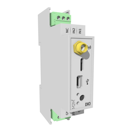
Page 7: Footprint And Installation
Footprint and installation Dimensions give in mm. ACW modems in ‘breaker’ format are attached to a DIN-rail. ATIM_ACW-DINDIO_868_UG_EN_V1.3... -
Page 8: Set Up
This version was designed for installation in an electrical box made of PVC or metal. If the cabinet is made of insulating material (PVC, ABS, fiberglass), it is possible to simply use a small whip-wave antenna: Ref ATIM ANT868-12FSC. This antenna must be firmly screwed on the SMA connector and positioned vertically, preferably upwards. -
Page 9: Configuration Du Modem
Configuration du modem Download and install the configuration software '' setupACW.exe '' at: http://www.atim.com/produit/atim-cloud-wireless-acw/ Connect the module to your computer with a USB cable and then launch the software. When you connect the module, the software window changes to allow you to access the main features. -
Page 10: Lights Meaning
o The modem address is the address of your ACW-DINDIO, each modem must have a different address. o The remote address is the address of the device with which you want to communicate. o TimeOut acts as a watchdog. It is configurable from 0 (disabled) to 10 seconds. If no frame has arrived at the product within this time, then the modem output goes to 0. -
Page 11: Frames Format
Modbus mode is commonly used with a Modbus master controller or with a supervisor connected to an ACW-RS ARM-SE. Download configuration software from: http://www.atim.com/product/atim-cloud-wireless-acw/la-new-gamera-atim-cloud-wireless The main functions are: • Digital inputs lecture • Lecture and writing of the digital output • Analogical input lecture (ACW-DA version) • Metering lecture and writing Modbus Slave configuration... -
Page 12: Modbus Master Configuration
Modbus Master configuration Modbus table Modbus Adress Data 0x00 (0) Digital inputs lecture b0: Input 1 state b1: Input 2 state 0x40 (64) Meter input 1 lecture and writing (b31 to b16) 0x41 (65) Meter input 1 lecture and writing (b15 to b0) 0x42 (66) Meter input 2 lecture and writing (b31... -
Page 13: Supported Modbus Functions
Supported Modbus Functions Function Type 0x03 (3) Various registers lecture 0x10 (16) Various registers writing Data decoding SLAVE FUNC START ADDR REG QTY BYTES COUNTER 1 COUNTER 1 COUNTER 2 COUNTER 2 COUNT Slave Id 1 octet Slave Modbus ID Code Function 1 octet 0x10... -
Page 14: Use Case
(and vice versa). In multiple mirror mode, it is possible to have a master module to several slave modules. The transmission is cyclic or triggered (change of state). Download the configuration software from: http://www.atim.com/product/atim-cloud-wireless- acw/la-new-gamera-atim-cloud-wireless Simple mirror mode between two ACW-DINDIO ACW-DIO... - Page 15 In this configuration, the master modem and the slave modem have identical configuration of the inputs and outputs, the master modem sends a radio frame representing the state of its inputs to the slave modem which copies the state of the received inputs to its outputs and which immediately returns the status of its entries to the master modem.
-
Page 16: Simple Mirror Mode Between A Acw-Di And A Acw-Dindio
Simple mirror mode between a ACW-DI and a ACW-DINDIO In this configuration, the master modem sends the frame on a change of state of its digital inputs to the slave modem. The ACW-DI with battery must be configured in master mode, it is him who will instantiate the communication during a change of state of its entry. -
Page 17: Multiple Mirror Mode
Multiple mirror mode In this configuration, there is a master modem and several slave modems. The master modem cyclically sends the state of its input to the slave modems. In this mode, slave modems do not respond to the master. The "@Remote" address of the master modem must be set to 0 in order to broadcast (broadcast to all slaves without distinction of address). -
Page 18: Help
• Check if the power supply is properly connected to the modem • USB Configure the modem using the USB configurator Technical support For any information or technical problems, you can contact our technical support by e-mail and phone: www.atim.com/fr/technical-support ATIM_ACW-DINDIO_868_UG_EN_V1.3...
Need help?
Do you have a question about the Cloud Wireless DINDIO and is the answer not in the manual?
Questions and answers