
Summary of Contents for ATIM Cloud Wireless DINRS
- Page 1 ATIM Cloud Wireless ® Bridge Mode RS232/485 DINRS User Guide Concerned models: ACW/SF8-DINRS [Software 2.3 Revision B.0 or previous] ACW/LW8-DINRS [Software 1.7 Revision A.3 or previous] ACW/868-DINRS ACW/868-DINRS+...
-
Page 2: Table Of Contents
ABLE OF ONTENTS Document version history ..............................3 Disclaimer ..................................3 Trademarks and copyright ..............................3 Declaration of compliance ..............................4 Environmental recommendations ............................ 4 Explosive atmosphere Environment Radio Technical specifications ..............................6 Installation ..................................7 Positioning Connecting the modem LEDs meaning Push button Modem configuration .............................. -
Page 3: Document Version History
Trademarks and copyright ATIM radiocommunications®, ACW ATIM Cloud Wireless® and ARM Advanced Radio Modem® are registered trademarks of ATIM SARL in France. The other trademarks mentioned in this document are the property of their respective owners. ATIM_ACW-DINRS_RS+_UG_EN_V1.5... -
Page 4: Declaration Of Compliance
Declaration of compliance All ACW Atim Cloud Wireless® products comply with the regulatory requirements of the R&TTE Directive (1999/5/EC), article 3: 1 SAFETY (Article 3.1a of the 1999/5/EC Directive) NF EN60950-1 Ed. 2006/A1:2010/A11:2009/A12:2011 (health) EN62479: 2010 (power <20mW) or EN62311:2008 (power > 20mW) 2 Electromagnetic compatibility (Article 3.1b of the 1999/5/EC Directive) -
Page 5: Radio
General hazard – Failure to follow the instructions presents a risk of equipment damage. Electrical hazard – Failure to follow the instructions presents a risk of electrocution and physical injury. Direct-current symbol WARNING: do not install this equipment near any source of heat or any source of humidity. WARNING: for your safety, it is essential that this equipment be switched off and disconnected from mains power before carrying out any technical operation on it. -
Page 6: Technical Specifications
Technical specifications Dimensions 90 x 57 x 67 mm Antenna External by SMA connector -20°C to +55°C (operating) Temperature -40°C to +70°C (storage) Mounts to DIN-Rail Power Supply 10-30Vcc Frequency 865 – 870 MHz Power (RS model) 25 mW (14 dBm) Power (RS+ model) 500 mW (27 dBm) Local: 1.2 to 115 Kbit/s... -
Page 7: Installation
This version was designed for installation in an electrical box made of PVC or metal. If the cabinet is made of insulating material (PVC, ABS, fiberglass), it is possible to simply use a small whip-wave antenna: Ref ATIM ANT868-12FSC. This antenna must be firmly screwed on the SMA connector is positioned vertically, preferably upwards. -
Page 8: Connecting The Modem
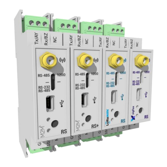
b. Connecting the modem Terminal blocks: Name Description In / Out Earth/Ground (Gnd) In (power supply) 10/30V Power supply between 10V and 30V Earth Not connected Tx/BZ RS232 Tx Output RS485 BZ Bidirectional/differential Rx/AY RS232 Rx Input RS485 AYm Bidirectional/differential Not connected Antenna (SMA): Before powering the product, a 50 Ω... -
Page 9: Push Button
In USB configuration mode, the green LED flashes until the configuration is completed and the USB cable is removed. Overall, in normal operation, the green LED illumination confirms an RS232 / 485 or radio communication. The red LED lights to indicate any errors that may occur. d. -
Page 10: Modem Configuration
Modem configuration Download and install the configuration software '' setupACW.exe '' at: http://www.atim.com/produit/atim-cloud-wireless-acw/ Connect the radio modem to your computer with a USB cable and then launch the software. When you are logged in, the software window changes to allow you to access the main features. -
Page 11: Bridge Mode Configuration (Sf8)
a. Bridge mode configuration (SF8) Attention Setup available for SF8 (Sigfox) references Software 2.3 Revision B.0 or prior. The following information applies to the ACW / SF8-DINRS. In this mode of operation, the data of the serial link is directly transmitted as such on the Sigfox network. Note: If the frames sent via the serial link are greater than 12 bytes these will be split into several frames of 12 bytes. - Page 12 ✓ 1: Serial parameters: The ACW-RS module has a serial link that you can set in RS232 or RS485 mode. You must also specify the speed (Baudrate) you want to use: 4800, 9600, 19200, 38400, 57600, and 115200 are available. The other default parameters (and not configurable for RS485 type links) are: 1 stop bit, no parity, no flow control and 8 data bits.
-
Page 13: Bridge Mode Configuration (868)
The following information applies to ACW / 868-DINRS and ACW / 868-DINRS +. In this operating mode, the data of the serial link is transmitted directly in local radio to another ATIM device (ACW / ARM) and vice versa. Typically, with another ACW / 868-DINRS or DINRS +. - Page 14 ✓ 3: Energy saving mode: This mode reduces the power consumption of the ACW-RS if it is set to 'Slave'. In this mode of operation, another ACW-RS must be configured in 'Master' mode so that communication between the two modems is possible. 'Disable' Disables this mode. ✓...
-
Page 15: Bridge Mode Configuration (Lorawan)
c. Bridge mode configuration (LoRaWAN) Attention Setup available for LW8 (LoRaWAN) references Software 1.7 Revision A.3 or prior. The following information applies to the ACW / LW8-DINRS. In this operating mode, the data of the serial link is transmitted directly to the LoRaWAN network. Note: Frames must not exceed 512 bytes. -
Page 16: Slave Modbus Configuration (Sf8 & 868)
d. Slave Modbus configuration (SF8 & 868) Attention For SF8 (Sigfox) versions, setup available for references Software 2.3 Revision B.0 or prior. The following information applies to the ACW / SF8-DINRS, ACW / 868-DINRS and ACW / 868-DINRS +. In this mode of operation, the ACW-DINRS is seen as a Modbus slave on the RS232 or RS485 serial link, as well as by the radio. - Page 17 ✓ 2: Modbus parameter: '@Modem' is the address of your ACW-DINRS. This is the Modbus ID by which the ACW-DINRS will respond. ✓ 3: Radio parameters: These are the radio settings that will need to be selected carefully according to the environment in which the ACW is installed.
- Page 18 Modbus slave mode Modbus table: Modbus address Default values Descriptions 60000 Octets 1 and 2 SIGFOX. 60001 Octets 3 and 4 SIGFOX. 60002 Octets 5 and 6 SIGFOX. 60003 Octets 7 and 8 SIGFOX. 60004 Octets 9 and 10 SIGFOX. 60005 Octets 11 and 12 SIGFOX.
- Page 19 0 dBm 5 dBm 7 dBm 10 dBm 12 dBm 14 dBm 20 dBm (only with ACW/868-DINRS+) 23 dBm (only with ACW/868-DINRS+) 27 dBm (only with ACW/868-DINRS+) 255 for an auto configuration. Note: Not all values are possible depending on the radio rate and the radio channel.
- Page 20 Supported Modbus Functions: Function Type 0x03 (3) Read Holding Registers 0x04 (4) Read Input Registers 0x10 (16) Write Multiple registers Note: You can read and write up to 50 registers in a single Modbus request. Note: You must respect a timeout of 10s if you send data to SIGFOX and a timeout of 500ms if you modify all the configuration registers (60007 to 60011).
-
Page 21: Modbus Slave Mode Configuration (Lorawan)
e. Modbus Slave mode configuration (LoRaWAN) Attention Setup available for LW8 (LoRaWAN) references Software 1.7 Revision A.3 or prior. The following information applies to the ACW / LW8-DINRS. In this operating mode, the ACW / LW8-DINRS is seen as a Modbus slave on the RS232 or RS485 serial link. Note: You can write up to 16 registers in a single Modbus request. - Page 22 ✓ 3: Modbus parameter: ‘@Modem’ corresponds to the address of your ACW / LW8-DINRS. This is the Modbus identifier with which the ACW / LW8-DINRS will respond. Slave Modbus mode Modbus table: Data written in any register is sent directly to the LoRaWAN network. Only the number of written records will be sent.
-
Page 23: Modbus Master Mode Configuration (Sf8)
f. Modbus Master Mode configuration (SF8) Attention Setup available for SF8 (Sigfox) references Software 2.3 Revision B.0 or prior. The following information applies to the ACW / SF8-DINRS. In this operating mode, the ACW / SF8-DINRS is viewed as a Modbus master on the RS232 or RS485 serial link. - Page 24 ✓ 3: Frames parameters: You can configure a maximum of 6 modbus frames. For each of the frames, you must specify the Modbus address of the slave '@Device' you wish to interrogate, the register (word 16bits) from which you want to read '@Registers' as well as the number of words 'Length' (max 4 words).
-
Page 25: Modbus Master Mode Configuration (Lorawan)
g. Modbus Master Mode configuration (LoRaWAN) Attention Setup available for LW8 (LoRaWAN) references Software 1.7 Revision A.3 or prior. The following information applies to the ACW / LW8-DINRS In this operating mode, the ACW / LW8-DINRS is seen as a Modbus master on the RS232 or RS485 serial link. ✓... - Page 26 ✓ 4: Frames parameters: You can configure a maximum of 6 modbus frames. For each frame, you must specify the Modbus address of the slave '@Device' that you want to query. The register (16-bit word) from which you want to read '@Registers' as well as the number of words 'Length' to read is also to be specified.
-
Page 27: Configuration Example
Configuration example a. Bridge Mode (868) The following information applies to ACW / 868-DINRS and ACW / 868-DINRS +. There are three ACW-DINRS, which will be noted here by ACW-A, ACW-B and ACW-M (Master). It is desired that ACW-M communicate with ACW-A and ACW-B, but that ACW-A and ACW-B communicate only with ACW-M (ACW-A and ACW-B do not see the frames of one or the other. -
Page 28: Slave Modbus Mode (Sf8 & 868)
b. Slave Modbus Mode (SF8 & 868) Attention For SF8 (Sigfox) versions, setup available for references Software 2.3 Revision B.0 or prior. The following information applies to the ACW / SF8-DINRS, ACW / 868-DINRS and ACW / 868-DINRS +. Conventionally, a PLC (or other Modbus master device) will be directly connected to an ACW-DINRS via an RS232 or RS485 serial link. - Page 29 Functional description: Imagine that you want to send three registers of PLC 1 and 3 registers of PLC 2 every 30 min: The idea would be to store / write 3 registers of the PLC 2 via radio to the ACW-S in these registers 60000 60002, for example every 15 min.
- Page 30 Configuration example: The ACW-S and the ACW-A have the same radio configuration. The ACW-B must have a different radio configuration than the ACW-S and the ACW-A. PLC 1 (or PLC 2 or the two PLCs) will write the radio configuration of the ACW-S allowing communication with the ACW-B. 1.
-
Page 31: Data Access On The Web (Sigfox And Lora Solutions)
Data access on the web (Sigfox and LoRa solutions) a. Viewing modems on the ACW platform Log in to the web platform http://acw.atim.com to access your devices and view your data. Your login details will be provided by email to the shipping of your order. -
Page 32: Register The Modem On The Sigfox Network
b. Register the modem on the SIGFOX network To register the modem with the SIGFOX network, open an Internet browser and go to https://backend.sigfox.com. Press "New" to add your device Enter ID Enter PAC Your product is now being imported into your SIGFOX account. The import may take several hours. ATIM_ACW-DINRS_RS+_UG_EN_V1.5... -
Page 33: Register The Modem On The Lorawan Network
c. Register the modem on the LoRaWAN network A Join request to a LoRa network is issued when the product is powered on. The device must first be provisioned on the required network, at one of the operators (Orange or Objenious for example) or existing private gateways. -
Page 34: Troubleshooting
• Check whether the power supply is correctly connected to the modem • Configure the modem using the USB configuration tool Technical support For any information or technical problem, you can contact our technical support on this page: www.atim.com/en/support-2/technical-support/ ATIM_ACW-DINRS_RS+_UG_EN_V1.5...
Need help?
Do you have a question about the Cloud Wireless DINRS and is the answer not in the manual?
Questions and answers