
Summary of Contents for MAXPhotonics MFSC
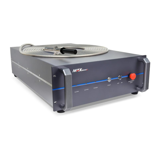
- Page 1 MFSC 2000W-3000W (Chassis Type) Single Module CW Fiber Laser Maxphotonics Co.,Ltd.
- Page 2 Copyright Notation Copyright © Maxphotonics Co ., Ltd ( here after referred to as Maxphotonics). All rights reserved. You may not copy, modify, transmit or publish this publication, in any form, in any media or by any means, without the prior written permission of Maxphotonics, except as allowed under applicable copyright laws.
- Page 3 Preface Thank you for using the MFSC Series CW fiber laser from Maxphotonics.We compile this document for you in order that the laser is used and maintained properly. Due to the limited level of the writers, coupled with time constraints, there are some careless mistakes in this document, your understanding and suggestion to help us make an improvement will be much appreciated .
-
Page 4: Company Profile
Company Profile Found in 2004, Maxphotonics is one of the first fiber laser manufacturers in China. It is also the first in China to realize independent intellectual property rights and vertical integration in the core technologies of fiber lasers and optical devices. -
Page 5: Table Of Contents
CONTENT Company Profile ……………………………………………………………… 2 Chapter 1 Characteristic Description …………………………………… 5 Chapter 2 General Safety Information …………………………………… 6 1-Safety Conventions …………………………………………………………… 6 2-Laser Protection ……………………………………………………………… 7 3-Reference Standard ………………………………………………………… 8 4-General Safety Instructions ………………………………………………… 9 5-Additional Safety Information ……………………………………………… 14 Chapter 3 Product Description ………………………………………………... - Page 6 CONTENT 6-Structural Layout ……………………………………………………………… 23 Chapter 5 Unpacking Guide ………………………………………………… 24 1-Unpacking Steps ……………………………………………………………… 24 2-Packing List …………………………………………………………………… 25 Chapter 6 Operation Guide …………………………………………………… 26 1-Notice …………………………………………………………………………… 26 2-Electrical Power Connection ………………………………………………… 26 3-Extension Interface …………………………………………………………… 27 4-Start Steps ……………………………………………………………………… 28 5-Mode Description ………………………………………………………………...
-
Page 7: Chapter 1 Characteristic Description
Characteristic Explain MFSC 2000W-3000W (Chassis Type) Single Module CW Fiber Laser is developed by Maxphotonics, provide a wide range of wavelength from 1060nm to 1100nm. The lasers are water-cooled and maintenance-free and with the efficiency is more than 30%. Maxphotonics' MFSC 2000W-3000W (Chassis Type) Single Module CW Fiber Laser are Class 4 laser products and are designed and tested with safety. -
Page 8: Chapter 2 General Safety Information
Chapter 2 General Safety Information 1-Safety Conventions All safety warning symbols during operating process of the laser include: SYMBOLS DESCRIPTION WARNING: Refers to a potential Electrical Hazard to human body. It requires a procedure that, if not correctly followed, may result in bodily harm to you and/or others. Do not proceed beyond the WARNING sign until you completely understand and meet the required conditions. -
Page 9: 2-Laser Protection
Chapter 2 General Safety Information NOTE : ◎ Maxphotonics' MFSC 3000W (Chassis Type) Single Module CW Fiber Laser . It may emit up to 3000W average power from 1060nm to 1100nm. This level of light may cause damage to the eye and skin. Despite the radiation being invisible, the beam may cause irreversible damage to the retina. -
Page 10: 3-Reference Standard
◎ In accordance with relevant EU and national standards and requirements, the laser must be classified according to its output power and laser wavelength. All MFSC-2000W-4000W-Series laser products with high power belong to Class 4 products (according to article 8, EN 60825-1). -
Page 11: 4-General Safety Instructions
Attention should be paid to related device protection. WARNING: ◎ The Maxphotonics MFSC laser light is strong enough to cut or weld metal, burn skin, clothing and paint. In addition, this light can ignite volatile substances such as alcohol, gasoline, ether and other solvents. During the operating process, the flammable materials around the laser must be isolated. - Page 12 Chapter 2 General Safety Information 1、Never look directly into the laser output port when the power is turned on. 2、Avoid positioning the laser and all optical output components at eye level. 3、Equip with laser beam casing. 4、Remove the end-cover before switch ON the laser. Or else the output head will be damaged irreversibly.
- Page 13 Chapter 2 General Safety Information Please note that any macroscopic attachment may cause extreme damage to lens or burn the laser or any backward-stage light path equipment. ◎ For cleaning instructions of the lens, please refer to the "Optical Fiber Connector Inspection and Cleaning Guide".
- Page 14 5、The equipment does not have any part which can be maintained by operators, and all the maintenance operations must be finished by the professionals of Maxphotonics Co., Ltd. 6、To prevent electrical shock, do not remove enclosure, detach the laser without permission and damage the relevant signs. Any product with unauthorized dismounting shall not be subject to warranty.
- Page 15 Chapter 2 General Safety Information and contact Maxphotonics. 3、Ensure that the work surface is properly vented. There may be gases, sparks and debris generated from the interaction between the laser and the work surface, and they could pose additional safety hazard.
-
Page 16: 5-Additional Safety Information
Chapter 2 General Safety Information 5-Additional Safety Information For additional information regarding Laser Safety, please refer to the list below: Laser Institute of America(LIA) 13501 Ingenuity Drive, Suite 128 Orlando,Florida 32826 Phone:407 380 1553,Fax: 407 380 5588 Toll Free:1 800 34 LASER American National Standards Institute ANSI Z136.1, American National Standard for the Safe Use of Lasers (Available through LIA) -
Page 17: Chapter 3 Product Description
Chapter 3 Product Description 1-Features MFSC Series CW fiber lasers are compact and efficient high power lasers developed for industrial application. Mainly used in the fields of drilling, cutting and welding. Main Features: 1、High-quality laser output 2、High power, high efficiency 3、High reliability, long service life... -
Page 18: 4-Certification
Additional message Can be null 4 - Certification Maxphotonics certifies that this equipment has been thoroughly tested and inspected and meets published specifications prior to shipping. Upon receiving your equipment, check whether the packaging and accessories have been damaged in transit. If damage is apparent, please contact Maxphotonics immediately. -
Page 19: 6-Back Panel Description
Chapter 3 Product Description 6-Back Panel Description ITEMS FUNCTION DESCRIPTION CTRL External control connector RS232 RS232 connector ETHERNET Ethernet interface AC 380V 360-440VAC power input POWER 360-440VAC power switch WATER OUT Water cooling output port(3/4 inch) WATER IN Water cooling input port(3/4 inch) OPTICAL OUTPUT Laser output connector 7-Optical Output Terminal... -
Page 20: Chapter 4 Specification
1 -Optics Characteristic Parameters Characteristics Test conditions Min. Nom. Max. Unit Operation mode CW/Modulated Polarization Random Output power MFSC-2000W 100% CW 2000 Output power MFSC-3000W 100% CW 3000 Tuning range of output power Emission wavelength 100% CW 1070 1080 1090... -
Page 21: 2-General Characteristic Parameters
Cooling Method Water Cooling ≥ 30 < 30 ℃ Ambient Temperature 24-26 20-23 ℃ Chiller Set Temperature ≥ 4 Hydraulic pressure MFSC-2000W Water Flow Requirements MFSC-3000W Water Flow Requirements MFSC-2000W Chiller Rated Cooling Capacity Requirements MFSC-3000W Chiller Rated Cooling Capacity Requirements... -
Page 22: 4-Qbh Water Cooling Condition
Chapter 4 Specification CAUTION : ◎ The Chiller needs to meet the requirements of the above table under the conditions of a circulating temperature of 40 ° C and an outlet temperature of 22 ° C. ◎ The above recommended water pressure requires the pressure drop of the main line Δp ≤... -
Page 23: 5-Installation Environment Requirements
Chapter 4 Specification Adapters DN25 (1 inch tube), length ≤ 2m 3/4 inch Low temperature water circuit water 3/4 inch cooling machine Inner diameter 4mm Inner diameter ≥ 8mm, length ≤ 20m Inner diameter Total length High temperature water circuit <1m (external light path) Adapters... - Page 24 Chapter 4 Specification NOTE : ◎ In order to ensure a good operating environment of the laser, to reduce the probability of failure due to condensation. We recommende to prepare an air- conditioned room for the laser, so that the temperature in the air-conditioned room is ≤...
-
Page 25: 6-Structural Layout
Chapter 4 Specification 6-Structural Layout Laser Three Views.(Unit:mm)... -
Page 26: Chapter 5 Unpacking Guide
Chapter 5 Disassembly Guide 1-Disassembly Step The laser belongs to the precise valuables, so Maxphotonics recommends the following steps to unpack the packing box. Please unpack according to the following steps: 1. Place the package containing the laser equipment on a horizontal platform, such as a floor or a large table. -
Page 27: 2-Packing List
CAUTION: ◎ If any damage of the external package and internal parts has been found upon receipt of product, please contact Maxphotonics Co., Ltd. or designated agent immediately. ◎ When the laser is turned off, the water cooler should also be turned off to prevent condensation from occurring due to excessive temperature difference. -
Page 28: Chapter 6 Operation Guide
Poor contact of the ground wire may cause potential damage to the laser. For ensuring the safety feature, Maxphotonics recommends you connect a 32A circuit breaker (air switch) in series between the power supply unit and the laser. -
Page 29: 3-Extension Interface
Chapter 6 Operation Guide 3- Extension Interface Laser The CTRL interface is a high quality DB25 interface that provides a variety of signals for functional control of the laser, as described below: 2000W-3000W DB25 interface Ctrl Interface Function Wire Color Notes Description Enable input +... -
Page 30: 4-Start Steps
Chapter 6 Operation Guide 4-Start Steps WARNING: ◎ Make sure that all the electrical connections (including cooling water connections) are connected prior to use. All the connectors must be held steady with screws if possible. ◎ When operating the laser, do not directly look at the output fiber and wear safety glasses. - Page 31 Chapter 6 Operation Guide power of the laser (pulse width adjustment, when the external control, the modulation signal corresponds to the mode). 3, external control: specific parameter settings through the board software interface. External Control Signal Timing Emission Enable Input Laser Modulation Input Power Input...
-
Page 32: 6-Software Description
Software", and download "G3 Series-Software Installation Guide", "NET4.6", "G3-Series-n.n.n.n". (The version is updated from time to time, subject to the official website announcement without notice.) URL:http://en.maxphotonics.com/En/Software.html (2) Decompress the downloaded compressed package, and install the operating environment (NET4.6) and monitoring software (G3-Series-n.n.n.n) referring to the "G3 Series-Software Installation Guide". - Page 33 Chapter 6 Operation Guide (4) Check whether the communication interface of the laser backplane is RS232 or EtherNet, connect it to the computer, and power on the laser. (5) Double-click the desktop "G3-Series" shortcut to open the monitoring software and enter the following connection interface. (6) If the laser backplane is an RS232 interface, the monitoring software communication mode is selected as COM (the default is COM), and the corresponding COM number is selected, and then click the "Login"...
- Page 34 Chapter 6 Operation Guide If the laser is powered on and the model can match the monitoring software, it will enter the following monitoring interface. (8) Click the "Login" button to connect the laser and enter the following monitoring interface.
- Page 35 Chapter 6 Operation Guide (9) Decrypt the page. Tips: For the specific details of software installation and instructions, please refer to the relevant instructions of the official website software.
-
Page 36: 7-Error List
Chapter 6 Operation Guide 7-Error List The fault alarm points set by the laser include: No. Message Description Trouble shooting Laser internal Operation leads to low output power of PD alarm light path testing laser such as low modulation frequency, fault low peak power, low cutting power. -
Page 37: Chapter 7 Fiber Connector Inspection And Cleaning Guide
The use of a dirty or damaged fiber connector can result in serious injury and/or laser damage. Maxphotonics is not responsible for any damage due to contaminated connectors. For cleaning a fiber connector, you need the following materials: 1、Powder-free rubber gloves or fingerstall... -
Page 38: 2-Operating Procedures
Chapter 7 Fiber Connector Inspection and Cleaning Guide instructions. 2-Operating Procedures Clean and maintain the fiber laser according to the following procedures: 1、Switch off the laser power, and place the key switch on position of “OFF” 2、Remove the black outer protective sleeve and leave the white inner cap on and clean the fiber connector exterior with optical cleaner, wipe it with a clean optical wipe and dry it with compressed air;... - Page 39 Chapter 7 Fiber Connector Inspection and Cleaning Guide 7-2 Install the fiber connector under microscope 7-3 Cleaning protective lens with swabs...
- Page 40 Chapter 7 Fiber Connector Inspection and Cleaning Guide 1、quartz 2、fiber cladding 3、fiber core 7-4 Actual image of the fiber surface damaged coating damaged scratch 7-5 Endface may be damaged...
- Page 41 CAUTION : ◎ It is hereby stated that damage to the fiber connector can occur due to mishandling, the use of incorrect cleaning procedures, or chemicals for cleaning. This is not covered by the Maxphotonics' warranty.
-
Page 42: Chapter 8 Service And Maintenance
◎ For ensuring that the repairs or replacement within the warranty scope can be carried out, and perfectly maintaining your interests, please submit application to the Maxphotonics or the local representative after finding the faults. Upon receiving our authorization, you need to pack the product in a suitable package and return it. -
Page 43: 2-Service Statements
Please call the Customer Service Department for other questions: 400-900- 9588. Your problems will be follow-up by our technical support group after verified. If the problems cannot be solved , you may need to return the product to Maxphotonics for further troubleshooting. -
Page 44: Chapter 9 Warranty Statements
Warranty Statements 1-General Clauses Maxphotonics Co.,Ltd. carries out warranty for any defect of the product caused by its material and production technology within the warranty period agreed in contract, and ensures that its product meet the relevant quality and specification requirements specified in the document under normal use condition. - Page 45 IMPORTANT: ◎ Within the warranty scope, purchasers must feed back within 31 days after finding the product defect. ◎ Maxphotonics does not grant any Third Party rights to repair or replace the parts, the equipment or other Maxphotonics products.
Need help?
Do you have a question about the MFSC and is the answer not in the manual?
Questions and answers