Advertisement
Quick Links
1573 Savoie
C. P . 4 Plessisville, Qc.
G6L 2Y6
TEL: 819-362-7207
FAX: 819-362-2045
www.leclerclooms.com
info@leclerclooms.com
Loom Prepared by:_____________
Inspected by:_________________
Date:____________________
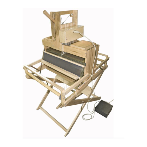
VOYAGEUR
16 SHAFT
COMPUTER-DOBBY
2120-1624
leclerc/INST_INDESIGN/voyageur16s/16s.indd
1
Advertisement

Subscribe to Our Youtube Channel
Summary of Contents for Leclerc VOYAGEUR
- Page 1 1573 Savoie C. P . 4 Plessisville, Qc. G6L 2Y6 TEL: 819-362-7207 FAX: 819-362-2045 www.leclerclooms.com info@leclerclooms.com Loom Prepared by:_____________ Inspected by:_________________ Date:____________________ VOYAGEUR 16 SHAFT COMPUTER-DOBBY 2120-1624 leclerc/INST_INDESIGN/voyageur16s/16s.indd...
- Page 2 The Loom shIpplng container includes the following: LOOM ASSEMBLED AND FOLD 16 SHAFT FRAMES AND 32 HEDDLE SUPPORTS SHAFT SELECTOR UNIT WITH SOLENOIDS UNIT STAND ASSEMBLED AND FOLD (2 TREADLES) BEATER ASSEMBLED WITH REED 12 DPI --- SS---...
- Page 3 INTERFACE BOX WITH CONNECTING CABLES 2 CRANK HANDLES 1000 INSERTED EYE HEDDLES (OR TEXSLOV) 2 SQUARE HEAD SCREWDRIVERS ( black, red) 1 BOAT SHUTTLE 1 REED HOOK 6141-0000 (10 5/8”) 2 METAL LEASE STICKS 2 METAL WARP RODS 2 SOFT WOOD BOARD (with black mark) 10x 18”...
- Page 4 2 Wood side loom strengthening piece 26 3/8" 6 Carriage bolts 1/4” x 3½” 6 Washers 1/4” 6 Nylon auto lock 1/4” 1 LOOP CORD 47” FOR TREADLE CONTROL 1 METAL WIRE/CHAIN 43” FOR TREADLE CONTROL 1 LOOP CORD 15", KNIFE TO HANDLE ATTACHMENT 2 MACHINE SCREWS ¼”X1½”...
- Page 5 Lay the loom on its back. Insert heddles in the heddle supports. Insert heddle supports in the shaft frame. Slide from the buttom of the loom each shaft frame . (Heddles support top and buttom slide inside side loom grooves) To make it nicer insert shaft frame so the twist in the top part is always on same side.
- Page 6 Install the Strengthening wood piece (S) on both side of the loom using: 6 Carriage bolts 1/4” x 3½” (C) 6 Washers 1/4” (W) 6 Nylon auto lock 1/4” (N) W + N If the back crank have been installed, you will have to remove it in order to insert from the back the strengthening piece.
- Page 7 Brake Spring Pulley Loop Cord Brake Lever Brake Circle Friction brake; Friction brake system on this loom have a brake lever, a loop so tension can be adjust easily, a spring, a brake circle and a brake drum. The brake loop cord pass outside of the loom and outside of the white pulley. To advance the cloth, lift the lever and turn the front beam.
- Page 8 LOOM STAND Lay the loom on one side; Assemble the front of the stand with the loom using 2 machine screws ¼” x 1½”. Note: The treadles are fixed to the back of the stand. Using the 2 carriage bolts ¼...
- Page 9 Install the beater to the loom using 2 round head screws #12, 1". Place a nylon spacer 5/16" between each swords and the wood. Do not over-tight so the beater can moove frealy and easily. Install the Warp and Cloth Beam Cranks.
- Page 10 Screw Knife Knife hook Make connection of the loop cord between the knife and the handle outside screw at black mark. Pass hole of black mark around the screw. The cord will probably have to be adjust later. If this cord is too tight, the action of the handle will be too hard.
- Page 11 Hammer Hammer Screw Gold Plate Rod Connect shaft frame loop cords to each hammer at the black mark. Just pass hole of black mark around each screw of the hammer. Make sure to pass loop cord INSIDE the gold plated rod as in the picture.
- Page 12 Install loop cord joining the screw hook of left treadle and hook under the knife, threading it between shaft frames. Adjust length so knife gets to the low position when the left treadle is depressed. Make sure that loop cord in the knife hook does not catch hammer when knife raise. Put end of cord in front of knife.
-
Page 13: Important Note
Install metal wire joining the screw hook of right treadle and screw hook at the back of the handle. Chain end’s goes to the treadle screw hook. Cable from the treadle have to pass between shaft frame 2 and shaft frame 3, then pass in front of the forward inside pulley to go to the handle... - Page 15 LOOM CONNECTION Make sure that the control box (Interface box) and computer are turned off and then connect the cables between: 1)Computer serial (com) port and the interface box. 2) Interface box and the solenoid unit. (Female to female cable) The standard cables supplied are for the PC Rs232 serial port.
-
Page 16: Starting The Unit
STARTING THE UNIT BEFORE YOU START SOFTWARE AND AFTER ALL CABLE ARE CONNECTED, PUT THE SWITCH OF THE BLACK BOX ON. LEAVE IT OPEN UNTILL YOU CLOSE SOFTWARE. MAKE SURE THE KNIFE IS IN DOWN POSITION. (HANDLE IN TOP POSITION) TO CHANGE ANY CONNECTION, PUT THE SWITCH OFF. -
Page 17: Maintenance
KNIFE ACTION The knife, as illustrated in the photograph, catches any fingers that have been pushed forward by the solenoid. It is VERY IMPORTANT that the knife is in the lower position before you start weaving (first selection) When you raise the knife with the front handle or Hammer the left treadle, the magnet (see page 7 picture), which is glued to the back of the knife, passes in front of... - Page 18 Adjust the height of the beater so the yarn just touch the shuttle race. Pull Push Loosen The beater has been adjusted here before shipping, but; if Loosen the batten doesn’t touch the two bumpers equally, loosen the bolts of the batten sley and batten handtree and exert pressure on the batten centering it in its proper place.
- Page 19 4) Slip a Bar thru each loop of all cords and pull tight.(See diagram) PROMPTLY CALL YOUR DEALER OR LECLERC FOR ANY QUESTIONS. We at Leclerc encourage Weaver feedback on this and all our products. Please send your comments to Leclerc Loom Co.
Need help?
Do you have a question about the VOYAGEUR and is the answer not in the manual?
Questions and answers