Table of Contents
Advertisement
Quick Links
Advertisement
Table of Contents

Subscribe to Our Youtube Channel
Summary of Contents for Turbosol T20X
- Page 1 ORIGINAL USE AND MAINTENANCE MANUAL T20X IS16/09 561400 Serial number Year...
- Page 2 THIS MANUAL IS PROPERTY OF TURBOSOL - ANY TOTAL OR PARTIAL REPRODUCTION IS STRICTLY FORBIDDEN...
- Page 3 THIS MANUAL IS PROPERTY OF TURBOSOL - ANY TOTAL OR PARTIAL REPRODUCTION IS STRICTLY FORBIDDEN...
-
Page 4: Table Of Contents
EMERGENCY STOP ........................53 NORMAL MACHINE STOP ......................53 REFUELLING ..........................53 START-UP ...........................54 WHAT TO DO IN CASE OF CLOGGING ..................56 5.10 WATER SYSTEM FOR MIXING WATER (OPTIONAL) ..............56 THIS MANUAL IS PROPERTY OF TURBOSOL - ANY TOTAL OR PARTIAL REPRODUCTION IS STRICTLY FORBIDDEN... - Page 5 HIGH WASHER PRESSURE (OPTIONAL) .................57 5.12 CLEANING THE MACHINE ......................60 MAINTENANCE ...................... 63 ROUTINE MAINTENANCE ......................63 EXTRAORDINARY MAINTENANCE ...................78 DEMOLITION ......................79 TROUBLESHOOTING ................... 81 THIS MANUAL IS PROPERTY OF TURBOSOL - ANY TOTAL OR PARTIAL REPRODUCTION IS STRICTLY FORBIDDEN...
-
Page 6: General Information
GENERAL INFORMATION Dear Customer Congratulations on your purchase of a TURBOSOL machine. Our long experience, attention to the needs of users and the continuous technological research allow us to offer high quality machines, reliable and long-lasting. Even if you have used this type of machine before, it is extremely important to be informed on the operation and features by the TURBOSOL PRODUZIONE S.p.A. -
Page 7: Machine Identification
GENERAL INFORMATION MACHINE IDENTIFICATION 1.1.1 Machine orientation Front F, rear R, left side S and right side D refer to the running direction of the machine. 1.1.2 Machine plate The machine plate is affixed on the rear of the left side. It bears the following information: CE Marking Installed power Manufacturer’s company name and address... - Page 8 GENERAL INFORMATION 1.1.3 Machine and engine serial number In addition to being indicated on the factory plate, the machine serial number is stamped on the chassis (Fig. 1-3). Engine serial number 1 is imprinted on the base (Fig. 1-4). 1.1.4 Road trailer identification plate If the machine has been approved as road trailer, the identification data is shown in plate 1 positioned inside the bonnet, above the radiator.
-
Page 9: Documentation Accompanying The Machine
GENERAL INFORMATION DOCUMENTATION ACCOMPANYING THE MACHINE The machine is delivered with the following documentation: - Use and Maintenance Manual - EC Declaration of Conformity - S.P.C. - Warranty certificate - Engine Use and Maintenance Manual - Trailer booklet - System diagrams EC DECLARATION OF CONFORMITY (FACSIMILE) 9/84 561400 - IS16/09 - EN... -
Page 10: Warranty Limits
The goods supplied by Turbosol Produzione S.p.A. but manufactured by third parties are covered by the warranty granted by the latter to Turbosol and that is applied to the Final user. Only the Manufacturing Company and the Organisations expressly authorised by it can intervene in the event of faults during the warranty period. -
Page 11: Information For Consultation
GENERAL INFORMATION INFORMATION FOR CONSULTATION This paragraph contains information useful for the understanding of the text in this Manual. 1.6.1 Unit of measurement The I.S. (Internal System) has been adopted for the unit of measurement. SIZE UNIT DEFINITION ALTERNATIVE UNIT OF MEASUREMENT Time second min (minute, 1 min = 60 s), h (hour, 1 h=3600 s) -
Page 12: Machine Presentation
MACHINE PRESENTATION MACHINE PRESENTATION TECHNICAL DATA Ø /Ø PIPING FOR MORTAR CONVEYOR 25/37 35/49 50/66 Nominal diameter Maximum operating pressure Connections Type Camlock 50M-35F DN-DN 35M-25M 50M-50F 35M-35F 1 Supplied with the machine SCREW PUMPS’ PERFORMANCE 60.12 Maximum granulometry 4÷6 8÷10 8÷10 8÷10... - Page 13 MACHINE PRESENTATION HIGH WASHER PRESSURE (Optional) Maximum pressure Standard nozzle 1504 G1/4 Rated flow rate l/min Minimum intake flow rate required l/min Maximum water intake pressure Maximum priming depth Maximum water temperature °C Minimum water temperature °C DIMENSIONS AND WEIGHTS Tipping mixer Rated capacity Flow rate...
-
Page 14: Type Of Machine
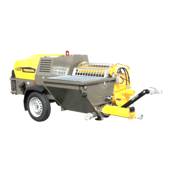
4 Do not use mineral oils or grease, as they deteriorate the stator rubber. TYPE OF MACHINE The T20X is a stationary machine for the transportation, distribution and projection of mortar. It is used autonomously and independently and is only intended for professional operators. -
Page 15: Main Components Of The Machine
Contact your Dealer or TURBOSOL PRODUZIONE S.P.A. directly to configure the machine in the most suitable manner for the type of activities to be performed. - Page 16 MACHINE PRESENTATION 2.6.2 Set-up for traditional mortars - T25 pump kit - 20 metre DN35 mortar conveying pipe with camlock fittings - 10 metre DN35 mortar conveying pipe with camlock fittings - 31 metre DN13 air hose with quick couplings - Traditional mortar gun with set of flaps - Accessory box 2.6.3...
- Page 17 MACHINE PRESENTATION 17/84 561400 - IS16/09 - EN...
-
Page 18: Safety And Prevention
The contents of this Manual are protected by laws for intellectual property protection. It is forbidden to reproduce, store, duplicate, reprocess, disclose this Manual or parts thereof, with electronic systems or other types and in any form, without the prior written permission of TURBOSOL PRODUZIONE S.p.A. 18/84... -
Page 19: Recipients Of Use
SAFETY AND PREVENTION RECIPIENTS OF USE The machine was designed to be operated by the following professional figures: OPERATOR Person trained and informed on residual risks, who deals with the supervision and running of the machine. Must be trained on the position of all control and safety commands. - Page 20 SAFETY AND PREVENTION 1000 mm 1400 mm MAINTENANCE TECHNICIAN Qualified technical personnel in charge of the extraordinary maintenance of the machine. The maintenance technician is trained and informed on residual risks but with the safety skills of the maintenance personnel to whom the maintenance of the machine is entrusted, except for the internal combustion engine.
-
Page 21: Main Warnings
SAFETY AND PREVENTION MAIN WARNINGS The user is responsible for training operators and maintenance technicians and properly implementing the instructions provided. The use and maintenance of the machine are only permitted to professional, trained and authorised operators and maintenance technicians. The use of the machine is forbidden to people with disabilities and minors. -
Page 22: Special Warnings For The Work Phases
SAFETY AND PREVENTION Do not use open flames near the machine. Always have a first aid kit and fire extinguisher at hand. Observe the maintenance intervals indicated in chapter 6 of the Manual. Only use original spare parts. SPECIAL WARNINGS FOR THE WORK PHASES The following paragraphs take into consideration the residual risks present during the various work phases and the requirements to avoid them. - Page 23 SAFETY AND PREVENTION Make sure that the trailer is properly connected to the towing vehicle before every trip. Observe the coupling angles of the ball joint: by overcoming these angles the components are excessively strained are the proper operation is no longer guaranteed (Horizontal ±20° and vertical ±25°). After the first trip and whenever a wheel is replaced: tighten the wheel fixing studs after a distance of at least 20 km and at most 100 km.
- Page 24 SAFETY AND PREVENTION 3.5.2 Lifting 3.5.2.1 Residue risks The lifting operations always involve a residual risk especially due to impacts, running over and/or crushing. These operations require a considerable degree of attention by the workers. The machine weight is given in the technical data in § 2.1. Do not stand underneath the suspended load.
- Page 25 SAFETY AND PREVENTION 3.5.3 Placement 3.5.3.1 Residue risks The placement operations always involve a residual risk especially due to abrasion, impacts and/or crushing. Use the drawbar to correctly position the machine. Stabilise the machine by positioning the parking wedges on the wheels and lower the outrigger base (clockwise rotation of the crank) to the ground.
- Page 26 SAFETY AND PREVENTION 3.5.4 3.5.4.1 Residue risks Below is a list of residual risks and description of the safety measures to eliminate them while using the machine. DANGERS ARISING FROM THE SAFETY SYSTEM FAULTS § 3.6 lists the safety devices and describes their respective operation. The operator is responsible for daily checking the smooth operation of the safety systems.
- Page 27 SAFETY AND PREVENTION The exposure to exhaust gases may be source of discomfort or irritation of the respiratory tract. Do not stand in front of the exhaust gas outlet. If you suspect intoxication, take the person concerned to the hospital. Do not expose dry grass, mown glass, oil or other combustible materials to the exhaust gas.
- Page 28 SAFETY AND PREVENTION Do not disconnect the pipes from the machine (conveying pipes and air pipes) if they are pressurised. Always discharge the residue pressure and then disconnect them (the mortar pump pressure gauge must be at zero bar, the pneumatic system valves must be open). In the absence of pressure the pipes sag when stepped on.
- Page 29 SAFETY AND PREVENTION DANGERS ARISING FROM THE FALLING OF OBJECTS The dangers arising from the falling of objects occur during machine tooling and tipping mixer loading; they are: - impact; - crushing; - tripping and falling; - projection of mortar. Carefully handle the objects used during machine use, such as, for example, tools, machine mobile parts (e.g.
- Page 30 SAFETY AND PREVENTION 3.5.5 Maintenance 3.5.5.1 Residue risks Below is a list of residual risks and description of the safety measures to eliminate the same while using the machine. For added safety during machine maintenance, also consider the residual risks set out in the previous paragraphs. DANGERS ARISING FROM THE LUBRICANTS The dangers arising from the lubricants, are: - damage to eyes and skin;...
- Page 31 SAFETY AND PREVENTION Ensure good ventilation in the area. Check the pouring point. Do not smoke. In case of accidental dispersion: Prevent the product from entering sewers and waterways; recover with the help of physical devices (e.g.: pumping); warn the competent authorities when the situation cannot be effectively and quickly resolved. Warn the competent authorities if the product is dispersed in waterways or sewers.
- Page 32 SAFETY AND PREVENTION Do not use or charge the battery if the electrolyte level is below the minimum notch. Add distilled water until the level is between minimum and maximum. Only check the charge status with voltmeter or densimeter. The battery may emit potentially explosive gases. Do not use naked flames or smoke near it. The battery electrolyte is toxic and corrosive.
- Page 33 SAFETY AND PREVENTION Repairs and extraordinary maintenance must be performed by authorised maintenance technicians. Before disconnecting any pipe, make sure there is no residual pressure inside (open all system valves). Wear adequate accident-prevention clothing (gloves, goggles). The pipes must always be in good conditions. The procedure for checking the pipes is set out in § 6.1.8. 3.5.5.2 Additional warnings The machine must be adequately cleaned before any maintenance intervention.
- Page 34 SAFETY AND PREVENTION 3.5.6 Disposal 3.5.6.1 Residue risks Below is a list of residual risks and description of the safety measures to eliminate them during the machine disposal. For added safety during machine disposal, also consider the requirements in the previous paragraphs. DANGERS ARISING FROM THE LUBRICANTS In this phase, the dangers arising from the lubricants, are the same set out in the maintenance paragraph.
- Page 35 SAFETY AND PREVENTION The components must be disassembled with the machine off and cold. Before disconnecting any pipe, make sure there is no residual pressure inside (open all system valves). Wear adequate accident-prevention clothing (gloves, goggles). 3.5.6.2 Additional warnings Cordon off the area where the disposal is carried out; it must be evident (e.g. through warning signs) that the machine cannot be used normally.
-
Page 36: Safety Devices
SAFETY AND PREVENTION SAFETY DEVICES The machine is equipped with the following safety devices: CONTROLS ENABLE BUTTON Pressing the button after starting the engine enables pumping, mixing and mixer movement; when the grids are closed the pumping or mixing do not automatically restart, but it is necessary to press the button. BONNET Interlocked mobile guard, PL=c in compliance with EN ISO 13849-1:2008. -
Page 37: Signs On The Machine
SAFETY AND PREVENTION SIGNS ON THE MACHINE The machine is fitted with labels having different purposes: Danger They inform the operator to act with caution and attention since there is a latent danger. The prohibition sign is triangular with a black frame, yellow background and black mark. - Page 38 SAFETY AND PREVENTION COMPULSORY SIGNS Body protection Protective helmet Protective gloves Safety footwear Protect the respiratory tracts: mask (Category II) Eye protection Hearing protection Read the use and Maintenance Lifting points maintenance manual performed only by before working qualified personnel Tab.
- Page 39 SAFETY AND PREVENTION 39/84 561400 - IS16/09 - EN...
-
Page 40: Transport And Installation
TRANSPORT AND INSTALLATION TRANSPORT AND INSTALLATION Observe the general safety requirements in § 3.4, those related to transport and use of P.P.E. in § 3.5.1. The operations listed below are the operator’s responsibility. The machine must be moved to the workplace using drawbar 1. TRANSPORT AS ROAD TRAILER Observe the maintenance intervals in chapter 6. - Page 41 TRANSPORT AND INSTALLATION - the locking handles are properly tightened and the safety split pins are present between the drawbar sections; - the lights cable is connected to the towing vehicle and is working; - the tyre pressure is correct; - foot 1 is fully raised.
- Page 42 TRANSPORT AND INSTALLATION - Guide the ball joint over the ball of the towing vehicle; - open the ball joint (Fig. 4-2); - raise the outrigger base (anti-clockwise rotation of the crank) until the ball joint engages correctly on the vehicle ball (Fig. 4- 3/4);...
-
Page 43: Lifting
TRANSPORT AND INSTALLATION LIFTING Observe the general safety requirements in § 3.4, those related to transport and use of P.P.E. in § 3.5.2. Lift the machine using lifting hook 1. INSTALLATION 4.3.1 Placement Observe the general safety requirements in § 3.4, those related to transport and use of P.P.E. in § 3.5.3. Find a safe and efficient position. - Page 44 TRANSPORT AND INSTALLATION 4.3.2 Pipe connection Check the pipes, gaskets and fittings as described in § 6.1.6-7-8-9. Lay the pipes and avoid them from twisting during mortar conveying. The first ten metres of piping are subject to oscillations (a few centimetres) during transport: it is advisable to raise this section from the ground and prevent it from resting on edges or abrasive elements.
- Page 45 TRANSPORT AND INSTALLATION Connect the mortar conveying pipe 1 and pneumatic pipe 2 to the machine. The pneumatic pipe must follow the path of the mortar conveying pipe. Connect the gun to the end of the pipe (when using the gun for common mortars, remove the gasket 1 from inside the fitting). Fully close the fitting and tighten it with safety spring 2.
- Page 46 TRANSPORT AND INSTALLATION If the machine is equipped with mixing water dosing system, connect the water supply pipe to fitting 1. 46/84 561400 - IS16/09 - EN...
- Page 47 TRANSPORT AND INSTALLATION 47/84 561400 - IS16/09 - EN...
-
Page 48: Use And Operation
USE AND OPERATION USE AND OPERATION Observe the general safety requirements in § 3.4, those related to transport and use of P.P.E. in § 3.5.4. PROCESSING PHASES Switching on the machine After completing the positioning phases described in the previous chapter, the operator on the machine starts the same as described in §... - Page 49 When lit during the engine operation, it indicates low engine oil pressure; the control system stops the engine after 5 seconds from switch-on. CHARGE STATUS INDICATOR (RED) When lit, it indicates the malfunction of the alternator. Tab. 5-1B 16 15 14 13 12 11 10 www.turbosol.it 49/84 561400 - IS16/09 - EN...
-
Page 50: Instruments On The Machine
USE AND OPERATION INSTRUMENTS ON THE MACHINE OPERATING MODE SELECTOR In this position the engine is always at maximum. In this position the engine automatically drops to idle speed when pumping is stopped by means of the pneumatic control. HIGH PRESSURE WASHER AND MIXING PRESSURE GAUGE It indicates the hydraulic mixing pressure and of the high pressure washer TIPPING MIXER LIFTING/DESCENT Lift the lever to raises the mixer. - Page 51 USE AND OPERATION 51/84 561400 - IS16/09 - EN...
-
Page 52: Description Of The Gun Components
USE AND OPERATION DESCRIPTION OF THE GUN COMPONENTS Below is a list of the main components of a projection gun. Certain types of gun do not have components. FLAP The mortar and air inside the flap come together and create the projecting rose. NOZZLE LOCKING It locks the nozzle in the desired position. -
Page 53: Emergency Stop
USE AND OPERATION EMERGENCY STOP In case of danger, stop the machine by pressing the emergency button. Press the button to stop the machine. Press and turn the button clockwise (as shown on the button) to disarm it. NORMAL MACHINE STOP Before stopping the engine, run it idle and empty for at least 5 minutes;... -
Page 54: Start-Up
USE AND OPERATION START-UP Carry out the necessary daily checks described in § 6.1. The bonnet must be lowered and closed and locks 1 at the sides of the machine closed. The engine air inlets must be free. Check that the mixer and hopper grids are closed. Make sure that the emergency button is not engaged. - Page 55 USE AND OPERATION Do not repeatedly and insistently start (not more than 15 seconds), the starter motor may brake. Warm up the engine idle for a few minutes. For low temperature start-ups, refer to the Engine manual. Prepare the slurry (50% water an 50% cement) to lubricate the pipes before transport and spraying. If you have to convey/spray ready-mixed mortar, use such mortar as slurry over-dosing the water with respect to the manufacturer’s instructions.
-
Page 56: What To Do In Case Of Clogging
USE AND OPERATION WHAT TO DO IN CASE OF CLOGGING The most dangerous situation during pumping is the clogging of the conveying pipe. In this condition the mortar pump pressure gauge indicates pressures higher than those of normal operation and the mortar no longer flows from the pipe. 5.9.1 Clogging of the conveying pipe The pipe between the mortar pump delivery and the clogging, is extremely rigid. -
Page 57: High Washer Pressure (Optional)
USE AND OPERATION 5.11 HIGH WASHER PRESSURE (OPTIONAL) If the machine is equipped with high pressure washer, it must be used to clean the machine after use. Only use clean water and observe the limits of use indicated in § 2.1. Do not use the high pressure washer without water supply. - Page 58 USE AND OPERATION Firmly grasp the water gun and pay attention to the reaction force of the high pressure water jet. Do not direct the high pressure jet towards materials containing health damaging substances. Do not modify or tamper with the high pressure washer. Before disconnecting the pipe and nozzle with high pressure washer deactivated, pull the trigger to release the residual pressure.
- Page 59 USE AND OPERATION 5.11.1 Mains water supply Connect the water intake pipe to the supply fitting Fig. 5-7.1. Connect the high pressure pipe 1 to the high pressure washer 2 delivery fitting; connect nozzle 3 to pipe 1. Pull the water gun trigger and wait for the water to come out from the nozzle (water not under high pressure); this is used to trigger the high pressure washer.
-
Page 60: Cleaning The Machine
USE AND OPERATION Activate the high pressure washer by lifting the selector on the control panel. Pull the nozzle trigger and wait for a water jet to come out (not under high pressure); this procedure is used to trigger the high pressure washer. Now close the regulator on the water gun Fig. - Page 61 USE AND OPERATION Also drain the residual water from the water system. Leave the valves open to discharge the water and protect the system in case of low temperatures. After cleaning, turn off the machine. Place the mortar pump selector, mixer and high pressure washer in neutral position. Turn the key to 0 and remove it.
- Page 62 USE AND OPERATION 62/84 561400 - IS16/09 - EN...
-
Page 63: Maintenance
MAINTENANCE MAINTENANCE Observe the safety requirements in chapter 3. Only use original spare parts. ROUTINE MAINTENANCE Remember that routine maintenance is the user’s responsibility. Refer to the Engine manual for the engine routine maintenance. Engine air filter cartridge check § 6.1.1 Engine air filter cartridge replacement §... - Page 64 MAINTENANCE 6.1.1 Check and replacement of the engine air filter When When beginning work Machine state With machine off and cold Tools Visual inspection None Remove lid 1 by opening flaps 2. The filter is composed of two cartridges, the outer one 1 (first stage) and the inner one 2 (second stage). Manually pull out the first stage cartridge;...
- Page 65 MAINTENANCE Introduce the first stage cartridge and close with the lid. Replace the cartridges observing the frequencies indicated in Tab. 6-1. 6.1.2 Compressor oil level check When When beginning work Machine state With machine off and cold Tools Visual inspection None Top-up No.19 wrench and funnel...
- Page 66 MAINTENANCE If after a few consecutive checks the oil level is significantly reduced, it is possible that the compressor leaks. Contact the Dealer or the TURBOSOL PRODUZIONE S.P.A. technical assistance to resolve the fault. 6.1.3 Hydraulic oil level check When...
- Page 67 If you cannot find the source of the leak, contact the Dealer or the TURBOSOL PRODUZIONE S.P.A. technical assistance to resolve the fault. 6.1.4...
- Page 68 An abnormal consumption of cooling liquid implies leaks from the cooling system. Check the system pipes and their fastening; if you cannot find the cause of the leak, contact the Dealer or the TURBOSOL PRODUZIONE S.P.A. technical assistance to resolve the fault.
- Page 69 MAINTENANCE 6.1.7 Conveying pipe anchor check When When beginning work Anchor state Clean, not released from the conveying pipes Tools Visual inspection None Check the good condition of the anchors: the metal parts must not be damaged or rusty, the rubberised canvas parts must not be cut or torn.
- Page 70 MAINTENANCE 6.1.11 Greasing When At end of work Machine state With machine off Tools Grease pump supplied (usable grease indicated in § 2.1) Grease through the lubricators on the machine. Agitator support Tipping mixing supports Tipping mixer lifting cylinder joints Mixer supports If greasing is performed correctly, grease must come out.
- Page 71 MAINTENANCE 6.1.12.1 State of wear When When beginning work Machine state Machine running Tools Mortar pump calibration system No.24 wrench for clamp screws Checking the state of wear of the pump is necessary to guarantee constant performances. The state of wear must be carried out periodically or when a reduction in performance is detected during the mortar conveying.
- Page 72 MAINTENANCE 6.1.12.2 Mortar pump replacement When As needed Machine state With machine off Tools No.19 wrench for rotor/shaft connection screw No.24 wrench for clamp screws and tie-rods Open the hopper grid then loosen and remove screw 1 that connects the rotor head to the stirrer. Replace the screw and bolt and worn/damaged.
- Page 73 After removing the rotor, check if it can be reused. The outer diameters of the rotors of the pumps provided by TURBOSOL PRODUZIONE S.P.A. are shown in Tab. 6-2.
- Page 74 MAINTENANCE The screw head hole must be at approximately 85 mm from the intake section of the stator for it to be connected to the stirrer. 85 mm To assemble the pump follow the disassembly instructions in reverse order, remembering that this must be done with the machine off.
- Page 75 MAINTENANCE Clean the cogwheels at the ends of the drawbar sections. 6.1.15 Fuel tank filling filter check When At end of work Machine state With machine off Tools Visual inspection None Open cap 1 of the fuel tank and remove the filling filter 2. Check that it is clean; if not, blow compressed air on it being careful not to damage the filter net.
- Page 76 MAINTENANCE 6.1.17 Battery replacement When As needed Machine state With machine off and cold Tools No.13 wrench to fix the battery No.9 wrench for the battery poles Check that the battery cut-off switch is disconnected. Disconnect the negative pole (-) 1, the positive pole (+) 2 and disassemble the battery stop 3. Replace the battery with a new and original one or with one having features not inferior to those indicated in the technical data.
- Page 77 MAINTENANCE If the filter is damaged or you are not sure of its good condition, replace it with a new and original one. 6.1.19 High pressure washer oil level check When When beginning work Machine state With machine off and cold Tools Visual inspection None...
-
Page 78: Extraordinary Maintenance
MAINTENANCE EXTRAORDINARY MAINTENANCE The machine extraordinary maintenance must be carried out by the maintenance technician. The extraordinary maintenance of the engine must be performed by personnel authorised by the engine manufacturer. Engine oil ◊ Engine oil filter cartridge ◊ ♦ Fuel filter cartridge ◊... -
Page 79: Demolition
DEMOLITION DEMOLITION Observe the safety requirements in chapter 3. The operations to be performed are those for the scrapping of: - steel, copper, aluminium parts (metal alloys in general); - rubber and plastic compounds; - insulating materials; - lubricating materials; - batteries and their fluids;... - Page 80 DEMOLITION 80/84 561400 - IS16/09 - EN...
-
Page 81: Troubleshooting
TROUBLESHOOTING This chapter sets out the common problems that can arise and the possible solutions. Contact your Dealer or the TURBOSOL PRODUZIONE S.P.A. technical assistance if the problem cannot be resolved or for different anomalies from those listed below. For any engine-related problems, consult the Engine manual or directly contact a KUBOTA authorised workshop. - Page 82 Clamp excessively tight Loosen the clamp screws Mixture cannot be pumped (e.g. Evacuate the mixture from the Blocked mortar pump excessive inert granulometry) machine Contact a TURBOSOL Hydraulic circuit fault PRODUZIONE S.P.A. authorised workshop Function off Activate the selector Mortar pump stopped...
- Page 83 TROUBLESHOOTING FAULT POSSIBLE CAUSE SOLUTION Check the integrity of the intake Air suctioned. circuit The high pressure washer does Delivery closed (e.g. in case of a not prime. Reset the delivery pressure by high pressure washer, water gun pressing the water gun lever closed) Check that the water mains flow rate Insufficient water supply or priming...
- Page 84 TROUBLESHOOTING 84/84 561400 - IS16/09 - EN...
Need help?
Do you have a question about the T20X and is the answer not in the manual?
Questions and answers