Table of Contents
Advertisement
Quick Links
Advertisement
Table of Contents

Related Manuals for SteelMax Rail Runner Gen III


Summary of Contents for SteelMax Rail Runner Gen III
- Page 1 The tools of innovation. OPERATOR’S MANUAL WELDING CARRIAGE 112 Inverness Circle East Suite F Englewood, CO 80112 1– 87STEELMAX, FAX 303 – 690 – 9172 www.steelmax.com sales@steelmax.com...
-
Page 2: Table Of Contents
Contents 1. GENERAL INFORMATION ....................3 1.1. Application ......................... 3 1.2. Technical data......................4 1.3. Equipment included ....................5 1.4. Dimensions ........................ 6 1.5. Design ........................7 2. SAFETY PRECAUTIONS ....................8 3. STARTUP AND OPERATION ..................10 3.1. Assembling the hi-flex, semi-flex, or rigid track............10 3.2. -
Page 3: General Information
1. GENERAL INFORMATION 1.1. Application The Rail Runner Gen III is a track carriage designed to make butt and fillet welds with or without oscillation and to cut. The carriage allows MIG/MAG, TIG, oxy-fuel, or plas- ma torches. The track is clamped with magnetic units to ferromagnetic surfaces that are flat or curved. -
Page 4: Technical Data
Oscillation speed 10–200 cm/min (5–78 in/min) Oscillation dwell time at center and on ends 0–5 s Required ambient temperature 0–50°C (32–122°F) Maximum allowed ambient humidity non-condensing Protection level IP 20 Weight 13 kg (29 lbs) Rail Runner Gen III Operator’s Manual... -
Page 5: Equipment Included
6.5 m (21 ft) arc ignition cable 1 unit Power cord 1 unit 0.5 m (1.5 ft) cable 1 unit 3 m (10 ft) cable 1 unit 5 m (16.5 ft) cable 1 unit – Operator’s Manual 1 unit Rail Runner Gen III Operator’s Manual... -
Page 6: Dimensions
Rail Runner Gen III 1.4. Dimensions 510 mm (20″) 195 mm (7.7″) Rail Runner Gen III Operator’s Manual... -
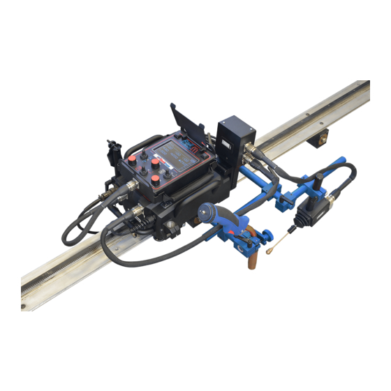
Page 7: Design
Carriage / cable connection Arc ignition socket Front cover Carrying handle Rod holder Power cord Passive roller Drive clutch knob Mounting bracket Pressing roller Limit switch Drive gear Pressing lever (pressing rollers are loose in this position) Rail Runner Gen III Operator’s Manual... -
Page 8: Safety Precautions
20. Do not bend the hi-flex track to a radius less than 0.75 m (2.5 ft). 21. Do not bend the semi-flex track to a radius less than 5 m (16.5 ft). 22. Use the rigid track only on flat surfaces. Rail Runner Gen III Operator’s Manual... - Page 9 31. Do not leave the carriage unattended during work. 32. If you are not going to use the carriage, remove it from the worksite and keep in a safe and dry place. Rail Runner Gen III Operator’s Manual...
-
Page 10: Startup And Operation
(1, Fig. 2) and of the racks (2). Next, attach the rails, clamp them with levers, and then tighten the connecting plates. Put the rack adjustment tool (not included) into the hole (3), and rotate the tool to the Rail Runner Gen III Operator’s Manual... - Page 11 (4) to remove the gap (5) between the racks. Then, tighten the leftmost screw and the rightmost screw of each rack (2). Fig. 2. Removing the gap between the racks of a semi-flex track Rail Runner Gen III Operator’s Manual...
-
Page 12: Assembling The Ring Track
Next, for all rails, use the 12 mm hex wrench to set the hinge as shown in Fig. 4. Then, put the lock pin through the holes (1), and then rotate the wrench (2) to connect the rails. Rail Runner Gen III Operator’s Manual... - Page 13 (1, Fig. 5). Adjust each support equally to make the track concentric to the workpiece. Lock the supports with the nuts (2) or levers. Fig. 5. Attaching the ring track to the workpiece Rail Runner Gen III Operator’s Manual...
-
Page 14: Positioning On A Straight Track
(3) fully to move back the gear (4). Then, put the carriage so that the mounting brackets are on the rail (5, 6). Gear moved back Mounting bracket Mounting bracket montażowy Fig. 6. Putting the carriage on a straight track Rail Runner Gen III Operator’s Manual... - Page 15 Move the carriage slightly back and forth to make sure that there is a backlash. Not engaged × Engaged ✓ Fig. 7. Engaging the carriage with the track Rail Runner Gen III Operator’s Manual...
-
Page 16: Positioning On A Curved Track
Then, tighten the screws (1) and use the knob (4) to engage the gear with the rack as described in “Positioning on a straight track”. Fig. 8. Rotating the rollers for a curved track Rail Runner Gen III Operator’s Manual... -
Page 17: Preparing And Connecting
3 m (10 ft) / 5 m (16.5 ft) cable (2). Then, connect the carriage to the power source and put the torch and torch cables into the holders. 0.5 m (1.5 ft) cable 3 m (10 ft) cable Fig. 9. Connecting the carriage Rail Runner Gen III Operator’s Manual... -
Page 18: Connecting To The Welding Circuits
Make sure that the arc ignition cable is connected correctly. To do this, turn on the power of the carriage, and then set the arc ignition switch to TEST. This should enable the arc for a while. Rail Runner Gen III Operator’s Manual... -
Page 19: Operating
Operating mode Direction switch Oscillation switch (Forward/O/Backward) (TEST/O/I) Arc ignition switch (TEST/O/I) Fig. 11. Control panel with the main screen displayed Tab. 1 explains the symbols shown on the right of the main screen. Rail Runner Gen III Operator’s Manual... - Page 20 From –9.9 to +9.9 Oscillation offset. Rotate From –3.9 to +3.9 in [step: 0.05/0.02] From –2.5 to +2.5 Torch height Rotate (when the vertical From –1 to +1 in slide is connected). [step: 0.02/0.01] Rail Runner Gen III Operator’s Manual...
- Page 21 Square. The carriage travels only during oscilla- tion dwell time in left and right position. During oscillation, the carriage stops. During oscillation dwell time in center position the carriage fills the crater. Rail Runner Gen III Operator’s Manual...
- Page 22 [step: 1/0.5] 0–10 cm Backweld length (parameter available only when Rotate 0–4 in the stitch welding is set to ON). [step: 0.1] Press, hold, 0–30 s Crater fill time before welding. and rotate [step: 0.1] Rail Runner Gen III Operator’s Manual...
- Page 23 Sensitivity of the tracking system. Normal. Press, hold, and rotate Low. The torch adjusts slower to the welding seam. High. The torch adjusts faster to the welding seam. Rotate Unit of measure. Metric or imperial. inch Rail Runner Gen III Operator’s Manual...
- Page 24 To stop the travel, set the direction switch to ‘O’. After the work is finished, use the power switch to turn off the carriage. Then, unplug the carriage from the power source. Rail Runner Gen III Operator’s Manual...
-
Page 25: Adjusting The Pressure Of Rollers
If the carriage moves smoothly, use the 2.5 mm hex wrench to prevent rotation of each screw (4). Then, use the 8 mm flat wrench to tighten the nuts (3). Fig. 13. Adjusting the pressure of rollers Rail Runner Gen III Operator’s Manual... -
Page 26: Adapting For Seam Tracking (Option)
Make sure that the carriage travels in the direction (7) to be able to track the seam correctly. Fig. 14. Changing the basic configuration to the seam tracking configuration Rail Runner Gen III Operator’s Manual... - Page 27 If the vertical slide is not used, connect the sensor to the carriage with the 1 m (3 ft) cable. 0.8 m (2.6 ft) cable 0.5 m (1.5 ft) cable Fig. 15. Connecting the tracking sensor to the carriage Rail Runner Gen III Operator’s Manual...
- Page 28 Install the torch into the torch holder. Then, tilt the rod of the sensor against the workpiece so that there is tension in the rod. Next, put the tip as shown in Fig. 16. Fig. 16. Setting the tracking sensor correctly Rail Runner Gen III Operator’s Manual...
- Page 29 Then, the oscillator, the vertical slide, and the torch, are moved to maintain the correct position above the seam. Fig. 17. Torch moves with small changes in position of the seam Rail Runner Gen III Operator’s Manual...
-
Page 30: Troubleshooting
Controller failure. Contact service center for check and repair. Motor overload. Adjust the position of the cables so that they do not block the carriage. Remove obstacles that block the carriage or the drive gear. Rail Runner Gen III Operator’s Manual... -
Page 31: Maintenance
3. Clean the torch nozzle and replace if damaged. Each month: 1. Make sure that the knobs and the switches work as intended. Replace if they are loose or damaged. 2. Examine cables and replace if damaged. 3. Tighten screws if loose. Rail Runner Gen III Operator’s Manual... -
Page 32: Accessories
(including 1 m (3 ft) cable): CZJ-0654-05-00-00-0 5.2. Tracking sensor tips Allow seam tracking in various applications. Part number: WSP-0523-07-01-13-0 (rod required for sensor tips) Part number: ADT-0506-40-00-00-0 Part number: ADT-0506-41-00-00-0 Part number: ADT-0506-43-00-00-0 Rail Runner Gen III Operator’s Manual... -
Page 33: Motorized Vertical Slide
Allows the vertical position of the torch to be controlled. Part number (including 0.8 m (2.6 ft) cable): OSK-0654-04-00-00-0 5.4. 0.5 m (1.5 ft) cable Required for connecting the motorized vertical slide to the tracking sensor. Part number: PWD-0654-06-00-00-0 Rail Runner Gen III Operator’s Manual... -
Page 34: Hi-Flex Track
If you need to use more units, use narrow magnetic units. Part number (rail): TRO-0673-00-00-00-0 Part number (rollers for hi-flex track): ZSP-0673-07-00-00-0 Use the 13 mm flat wrench to remove the standard rollers and install the rollers for hi- flex track. Rail Runner Gen III Operator’s Manual... -
Page 35: Semi-Flex Track
Allows guiding the carriage along a straight line. The length of a single rail is 2 m (6.5 ft). Part number: PRW-0482-47-00-00-0 5.8. Rack adjustment tool Removes the clearance between the racks of two semi-flex rails that are put on a curve. Part number: PKT-0341-13-00-00-0 Rail Runner Gen III Operator’s Manual... -
Page 36: Contact Block
Use two blocks to close the track and limit the travel path to a section. Part number Part number (for semi-flex and rigid track): (for hi-flex track): ZDR-0523-76-00-00-0 ZDR-0673-08-00-00-0 Rail Runner Gen III Operator’s Manual... -
Page 37: Magnetic Units
20°C (68°F) 75% (900 N) 80°C (176°F) 160°C (320°F) 50% (600 N) 120°C (248°F) 200°C (392°F) Use the 4 mm hex wrench to attach the unit to the tracks as shown in the figures. Rail Runner Gen III Operator’s Manual... - Page 38 Rail Runner Gen III M6x16 M6x16 M6x20 M6x20 M6x35 M6x16 Rail Runner Gen III Operator’s Manual...
- Page 39 80°C (176°F) 50% (600 N) 120°C (248°F) Install the unit in the same way as the magnetic unit is installed. To adjust the angle, use the 6 mm hex wrench and loosen four side screws. Rail Runner Gen III Operator’s Manual...
- Page 40 50% (600 N) 120°C (248°F) Install the unit in the same way as the magnetic unit is installed. To adjust the spac- ing, use the 5 mm hex wrench and loosen four side screws. Rail Runner Gen III Operator’s Manual...
- Page 41 20°C (68°F) 75% (750 N) 80°C (176°F) 50% (500 N) 120°C (248°F) Use the 4 mm hex wrench to attach the unit to the tracks as shown in the figures. M6x16 M6x16 M6x16 M6x16 Rail Runner Gen III Operator’s Manual...
-
Page 42: Semi-Flex Track Support
5.11. Semi-flex track support Allows supporting a semi-flex track by using the support instead of a magnetic unit or narrow magnetic unit. Use the 4 mm hex wrench to attach the support. Part number: WSP-0523-12-01-00-1 M6x16 Rail Runner Gen III Operator’s Manual... -
Page 43: Vacuum Track System
Allows clamping a hi-flex, semi-flex, or rigid track to non-ferromagnetic surfaces. Part number (vacuum pump with safety reservoir): AGR-0541-10-10-00-0 (115 V UK) AGR-0541-10-20-00-0 (230 V CEE) Other parts of the system are described in a related manual. Rail Runner Gen III Operator’s Manual... -
Page 44: Ring Tracks
Min. Max. [mm] [mm] TRO-0523-14-00-00-0 TRO-0523-78-00-00-0 TRO-0523-20-00-00-0 TRO-0523-21-00-00-0 TRO-0523-23-00-00-0 TRO-0523-24-00-00-0 TRO-0523-25-00-00-0 TRO-0523-26-00-00-0 TRO-0523-22-00-00-0 TRO-0523-28-00-00-0 TRO-0523-29-00-00-0 TRO-0523-30-00-00-0 TRO-0523-31-00-00-0 TRO-0523-32-00-00-0 TRO-0523-33-00-00-0 1000 TRO-0523-34-00-00-0 1000 1050 TRO-0523-35-00-00-0 1050 1100 TRO-0523-36-00-00-0 1100 1150 TRO-0523-37-00-00-0 1150 1200 TRO-0523-38-00-00-0 Rail Runner Gen III Operator’s Manual... - Page 45 TRO-0523-64-00-00-0 2500 2550 TRO-0523-65-00-00-0 2550 2600 TRO-0523-66-00-00-0 2600 2650 TRO-0523-67-00-00-0 2650 2700 TRO-0523-68-00-00-0 2700 2750 TRO-0523-69-00-00-0 2750 2800 TRO-0523-70-00-00-0 2800 2850 TRO-0523-71-00-00-0 2850 2900 TRO-0523-72-00-00-0 2900 2950 TRO-0523-73-00-00-0 2950 3000 TRO-0523-74-00-00-0 3000 3050 TRO-0523-75-00-00-0 Rail Runner Gen III Operator’s Manual...
-
Page 46: Ring Track Supports And Bracket
5.14. Ring track supports and bracket Ring track support with bolts Part number: WSP-0523-14-02-00-0 Ring track support with plastic feet Part number: WSP-0523-14-11-00-0 Ring track support with magnets Part number: WSP-0523-14-12-00-0 Ring track bracket Part number: DYS-0523-14-14-00-0 Rail Runner Gen III Operator’s Manual... -
Page 47: Torch Holders, Clamps, And Rods
Short low rod torch holder with clip 16–22 mm Part number: UCW-0476-06-00-00-0 Long rod torch holder with clamp 16–22 mm Part number: UCW-0466-04-00-00-0 Long rod torch holder with clip 16–22 mm Part number: UCW-0466-22-00-00-0 Rail Runner Gen III Operator’s Manual... - Page 48 Rail Runner Gen III Torch clamp 16–22 mm Part number: ZRZ-0466-04-01-00-0 Torch clip 16–22 mm Part number: ZCS-0476-06-01-00-0 Torch clamp 22–35 mm Part number: ZRZ-0466-19-00-00-0 Short rod Part number: WLK-0476-20-01-00-0 Long rod Part number: WLK-0466-04-10-00-0 Rail Runner Gen III Operator’s Manual...
-
Page 49: Transport Attachment
Rail Runner Gen III 5.16. Transport attachment Allows transporting the wire feeder. Part number: PEP-0523-93-00-00-0 Rail Runner Gen III Operator’s Manual... -
Page 50: Pendulum Oscillator
Part number: Part number: KLM-0236-00-16-00-0 (203 mm rod) OSC-0497-01-00-00-0 KST-0525-11-00-00-0 (Clamping block) Part number: ZSL-0497-16-00-00-0 (230 V CEE) ZSL-0497-16-00-02-0 (230 V AU) ZSL-0497-16-00-03-0 (230 V UK, type G) ZSL-0497-16-00-04-0 (230 V IN, type D) Rail Runner Gen III Operator’s Manual... - Page 51 Assemble the oscillator with a 203 mm (8″) rod and a clamping block (1). Use the 80 mm (3″) rod to put the oscillator onto the carriage (2). Next, set the switch to the middle position (3) and connect the oscillator to the power supply (4, 5). Rail Runner Gen III Operator’s Manual...
-
Page 52: Exploded Drawings And Parts List
5* UCW-0466-22-00-00-0 ROD TORCH HOLDER WITH CLIP ASSY ZRZ-0466-04-01-00-0 QUICK TORCH HOLDER CLAMP 16-22 RKJ-000036 HENDLEVER M6-32 TLJ-0419-04-02-03-0 INSULATION TUBE PKT-0466-04-01-10-0 KNOB KST-0466-43-04-00-0 DOUBLE CLAMPING BLOCK KST-0525-11-00-00-0 CLAMPING BLOCK RAM-0523-17-00-00-0 GUIDE ARM ZSP-0475-62-00-00-0 SLIDE Rail Runner Gen III Operator’s Manual... - Page 53 POWER CABLE 230V 32* PWD-0466-21-00-00-0 POWER CABLE 230V AUSTRALIA 32* PWD-0466-28-00-00-0 POWER CABLE 230V G TYPE, UK 32* PWD-0466-31-00-00-0 POWER CABLE 230V D TYPE, INDIA 33* PWD-0654-06-00-00-0 PANEL CABLE *not shown in the drawing Rail Runner Gen III Operator’s Manual...
- Page 54 NKR-000009 HEX NUT M3 WKR-000286 HEX SOCKET BUTTON HEAD SCREW M3x6 MDL-0654-80-05-00-0 CONTROLLER MODULE TLJ-000146 HEX SLEEVE M3/12 MDL-0523-03-03-00-0 PANEL MODULE MDL-0523-03-10-00-1 ENCODER MODULE PKT-0466-04-01-11-0 TORCH CLAMP KNOB OBD-0654-99-02-00-0 HOUSING - SERVICE RKJ-0523-03-12-00-1 HANDLE Rail Runner Gen III Operator’s Manual...
- Page 55 TORX SOCKET HEAD CAP SCREW M2.5x10 WZK-0526-02-02-03-0 TRAVEL DIRECTION SWITCH WIRE SET WZK-0523-03-13-00-1 NAVIGATION BUTTON WIRE SET PKT-000041 KNOOB PKR-000055 KNOOB COVER OSL-0523-03-14-00-0 PANEL COVER ZWS-0523-03-15-00-0 HINGE PRS-000111 O-RING SEAL 5x1.5 OSK-0523-03-16-00-0 HINGE AXIS Rail Runner Gen III Operator’s Manual...
- Page 56 HEX SOCKET HEAD CAP SCREW M4x14 SRB-000067 HEX SOCKET HEAD CAP SCREW M4x40 WSP-0523-02-06-00-0 BEARING BRACKET DYS-0523-02-08-00-0 SPACER I LOZ-000110 BALL BEARING 6x15x5 PAS-000009 TOOTHED BELT 140XL050 KOL-0654-01-03-04-0 GEAR WHEEL Z10 KOL-0654-01-03-03-0 MOTOR GEAR WHEEL Z10 Rail Runner Gen III Operator’s Manual...
- Page 57 DRIVE GEAR, T=14 PKT-0654-01-01-08-0 KNOB NKR-000017 HEX NUT M6 WSP-0654-01-01-13-0 RIGHT BRACKET SWK-0654-01-01-14-0 SLIDER KLK-000093 DOWEL PIN 8n6x50 TLJ-000048 SLIDE BUSHING 8x10x12 KRP-0654-01-01-16-0 ECCENTRIC HOUSNG DZW-0419-01-04-13-0 LEVER ZTR-0654-01-01-19-0 LATCH SPR-000065 SPRING KUL-0466-13-00-00-0 LEVER BALL MMS-0654-01-01-12-0 ECCENTRIC Rail Runner Gen III Operator’s Manual...
- Page 58 WKR-000313 HEX SOCKET BUTTON HEAD SCREW M3x8 SRB-000198 HEX SOCKET LOW HEAD BOLT M6x12 SRB-000060 HEX SOCKET HEAD CAP SCREW M3x6 SRB-000401 TORX SOCKET HEAD CAP SCREW M2.5x10 RLK-0341-01-02-00-0 PRESSURE ROLLER ASSY OPR-0654-01-01-17-0 SETTING Rail Runner Gen III Operator’s Manual...
- Page 59 DESCRIPTION Q-TY WKR-000330 HEX SOCKET BUTTON HEAD SCREW M4x20 PLY-0496-96-17-00-0 BOTTOM PLATE LOZ-000141 BALL BEARING 8x19x6 PRW-0523-06-01-20-0 GUIDE RAIL SRB-0523-06-01-03-0 SCREW KLK-000104 SPRING PIN 2x12 WKR-000091 HEX SOCKET BUTTON HEAD SCREW M4x8 OSL-0523-06-01-06-0 COVER Rail Runner Gen III Operator’s Manual...
- Page 60 PKR-000155 SOCKET COVER WZK-0654-04-01-11-0 TRANSMISION WIRE SET I DYS-0654-04-01-10-0 SPACER UCW-0654-04-01-05-0 MOUNT KLK-000052 DOWEL PIN 5n6x40 SRB-000398 HEX SOCKET HEAD CAP SCREW M4x35 33* PWD-0654-04-02-0 Z AXIS TRANSMISION CABLE *not shown in the drawing Rail Runner Gen III Operator’s Manual...
- Page 61 ELM-0523-07-01-14-0 SENSOR GUIDE PRT-0523-07-01-15-0 PROBE ROD STZ-0316-06-06-03-0 PROBE CONE KUL-0316-06-06-02-0 PROBE BALL UCW-0523-07-01-05-1 HOLDER PRT-0523-07-01-16-0 FORK PROBE GUIDE WSP-0523-07-01-10-0 SUPPORT KST-0525-11-00-00-0 CLAMPING BLOCK KLC-000060 1.5 MM HEX WRENCH KLC-000005 2.5 MM HEX WRENCH PLY-0523-07-01-01-0 FRONT PLATE Rail Runner Gen III Operator’s Manual...
- Page 62 Rail Runner Gen III ITEM PART NUMBER DESCRIPTION Q-TY RKJ-000036 HANDLEVER M6-32 KST-0466-43-04-00-0 DOUBLE CLAMPING BLOCK 31* PWD-0654-05-02-00-0 TRANSMISION CABLE *not shown in the drawing Rail Runner Gen III Operator’s Manual...
-
Page 63: Declaration Of Conformity
PROMOTECH sp. z o.o. ul. Elewatorska 23/1 15-620 Białystok Poland We declare with full responsibility that: Rail Runner Gen III Welding Carriage is manufactured in accordance with the following standards: • EN 60204-1:2006+A1: 2009 • EN 60974-10: 2007 • EN ISO 12100-1: 2010 and satisfies the regulations of the guidelines: 2014/30/EU, 2014/35/EU, 2006/42/EC, 2011/65/EU, 2012/19/EU. -
Page 64: Warranty Card
Serial number ........................ Date of sale ........................Signature and stamp of the seller .................. 0.02 / 8 October 2020 WE RESERVE THE RIGHT TO MAKE CHANGES IN THIS MANUAL WITHOUT NOTICE Rail Runner Gen III Operator’s Manual...
Need help?
Do you have a question about the Rail Runner Gen III and is the answer not in the manual?
Questions and answers