Table of Contents
Advertisement
Gate Swings Evenly and Freely
Post Bracket
Hung Firmly and Plumb
Secondary Opener
Power Cable
Fence Post Set in Concrete
This product meets the requirements of UL325, the standard for gate operator safety.
Mighty Mule® is the retail brand of Nortek Security & Control, LLC
Installation Manual
(For a single or dual gate installation)
Warning Sign
Gate Bracket
Horizontal Support
Horizontal Support
PVC conduit (not included)
to run second opener power
cable under driveway.
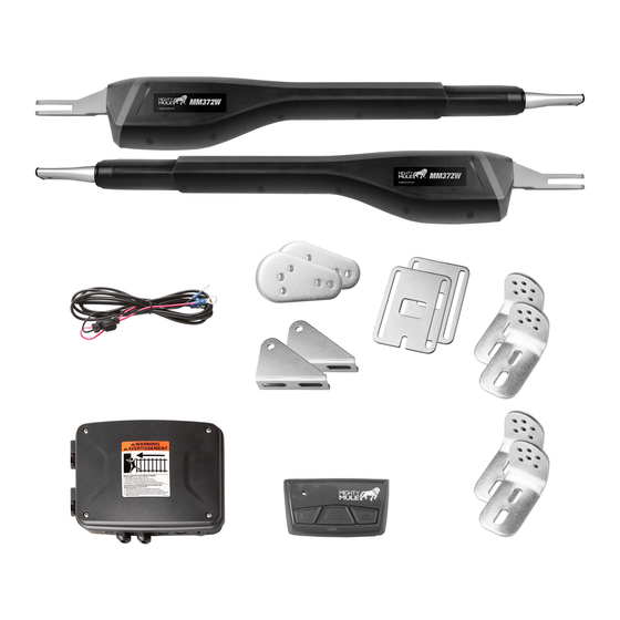
Dual gate installation [MM372W]
Example of Dual Gate finished installation
(Installations vary slightly on different types of gates)
MM371W
MM372W
Single gate installation [MM371W]
Warning Sign
Primary Gate Opener
Gate Bracket
Fence Post Set in Concrete
PVC conduit (not included)
to protect wire from lawn
mowers and weed eaters.
Post Bracket
Control Box
120 Volt indoor
Transformer
(surge protector
not supplied)
12 Volt automotive or marine
type battery in weather proof
housing (not included).
Run 1000' (max.) of low
voltage wire to control
box from transformer
(wire not included).
Advertisement
Table of Contents
Troubleshooting

Related Manuals for Nortek Control Mighty Mule MM371W

Summary of Contents for Nortek Control Mighty Mule MM371W
- Page 1 MM371W MM372W Installation Manual (For a single or dual gate installation) Single gate installation [MM371W] Gate Swings Evenly and Freely Post Bracket Post Bracket Control Box Hung Firmly and Plumb Warning Sign Warning Sign 120 Volt indoor Primary Gate Opener Secondary Opener Transformer Gate Bracket...
- Page 2 WARNING DO NOT SPLICE ANY POWER WIRES! DO NOT MODIFY THE BATTERY HARNESS! THIS WILL VOID YOUR MANUFACTURER’S WARRANTY. Low voltage wire for transformer not included.
- Page 3 WARNING This equipment meets Underwriters Laboratory Standard 325 (UL 325). However, gate equipment has hazards associated with its use and therefore by installing this product the installer and user accept full responsibility for following and noting the installation and safety instructions. Failure to follow installation and safety instructions can result in hazards developing due to improper assembly.
- Page 4 Vehicular Gate Operator Class Categories Residential Vehicular Gate Operator-Class I: Industrial/Limited Access Vehicular Gate Operator–Class III: A vehicular gate operator (or system) intended for A vehicular gate operator (or system) intended for use in an industrial use in garages or parking areas associated with a location or building such as a factory or loading dock area or other residence of one-to-four single families.
-
Page 5: Table Of Contents
Table of Contents Please Read This First! .......................... 2 Important Safety Information ......................... 3 Manually Opening and Closing Gate ..............................3 For the Installer and End User ................................4 Installing Warning Signs and Pedestrian Gates ..........................8 Required Safety Precautions for Gates ..............................9 Mighty Mule 371W/372W Gate Opener ............................10 Technical Specifications ........................ -
Page 6: Please Read This First
Please Read This First! Thank you for purchasing a Mighty Mule Gate Operator— The Mighty Mule Gate Operator also has an adjustable Nortek Security & Control's "do-it-yourself" automatic auto-close feature. After the gate reaches the fully open gate operator! When correctly installed and properly used, position, it can be set to remain open up to 120 seconds your Mighty Mule Gate Operator will give you many years before automatically closing. -
Page 7: Important Safety Information
Important Safety Information Because automatic gate operators produce high levels be completely exhaustive in nature. It does, however, of force, consumers need to know the potential hazards provide an overview of the safe design, installation, and associated with improperly designed, installed, and use of this product. -
Page 8: For The Installer And End User
Important Safety Information FOR THE INSTALLER AND END USER WARNING To reduce the risk of injury or death: 6. KEEP GATES PROPERLY MAINTAINED. Read the user’s manual. Have 1. READ AND FOLLOW ALL INSTRUCTIONS. a qualified service person make repairs to gate hardware. 2. - Page 9 Important Safety Information FOR THE INSTALLER AND END USER Typical Entrapment Zones are shown in the diagrams on page 4: Zone 1 – leading edge of the gate and the fence post. Zone 2 – between the gate and the gate post. Zone 3 –...
- Page 10 Important Safety Information FOR THE INSTALLER AND END USER III. After Installation 11. IMPORTANT: Save these safety instructions. Make sure everyone who is using or will be around the gate and 1. Attach the warning signs (included) to each side of the gate operator are aware of the dangers associated gate to alert the public of automatic gate operation.
- Page 11 Important Safety Information FOR THE INSTALLER AND END USER Mighty Mule gate operators utilize Dual Sense Technology One or more edge sensors may be located at the leading ™ entrapment protection. Dual Sense Technology is built edge, bottom edge, and post edge, both inside and outside ™...
-
Page 12: Installing Warning Signs And Pedestrian Gates
Important Safety Information INSTALLING WARNING SIGNS AND PEDESTRIAN GATES Warning signs alert people of automatic gate operation and are required when installing Mighty Mule Automatic Gate Operators. A minimum of two WARNING SIGNS must be installed in the area of the gate. Each sign is to be visible by persons located on the side of the gate on which the placard is installed. -
Page 13: Required Safety Precautions For Gates
Important Safety Information REQUIRED SAFETY PRECAUTIONS FOR GATES These warning labels should be found at the locations specified below. If any of them are missing, immediately contact Nortek Security & Control for replacements. WARNING AVERTISSEMENT Moving gate can cause injury or death! 1. -
Page 14: Mighty Mule 371W/372W Gate Opener
Technical Specifications MIGHTY MULE 371W/372W GATE OPENER _____________________________________ _____________________________________ DRIVE • Low friction screw drive (linear actuator) rated for -5 °F to +160 °F (-20 °C to +71 °C). • Powered by a 12 V motor with integral gear reducer. Motor speed reduced to 348 rpm at 12 V. •... -
Page 15: Powering Options
Before You Begin POWERING OPTIONS Determine Charging Option for Battery: Transformer OR Solar NEVER USE TRANSFORMER AND SOLAR PANEL(S) AT THE SAME TIME. It will damage the control board. IMPORTANT: ● The Mighty Mule 371 and 372 are designed and intended for use with a 12 Volt automotive, marine or lawn tractor battery. -
Page 16: Check Existing Gate Size And Material
CHECK EXISTING GATE SIZE AND MATERIAL • Gate size: Up to 16 feet and up to 550 lbs. — See • Type of gate material: Vinyl, aluminum, chain link, Operational Capacity chart on page 10. farm tube, wrought iron, wood. Not rated for use on solid surface gates. -
Page 17: Items Included For Primary Gate Opener Installation (Mm371W)
ITEMS INCLUDED FOR PRIMARY GATE OPENER INSTALLATION (MM371W) RP1010 Transformer Operator Closed Position Stop Plate Literature kit with gate warning signs MMT103 Transmitter Gate Bracket Control Box, Antenna & Battery Harness Post Brackets (2) Post Pivot Bracket 8” Nylon Cable Tie (10) 3/8”... -
Page 18: Tools Needed
TOOLS NEEDED 7/16” Bit Center Drill 1/2” Bit Punch 7/32” Bit Pliers Hammer 1/2” Hack Saw wrench Flat Head Screwdriver Philips Head Screwdriver 9/16” wrench Level Wire Small Tape Adjustable Clamps Stripper Flat Head Measure Wrench ITEMS NOT INCLUDED ● 12 Volt Auto or Marine Battery ●... -
Page 19: Mechanical Installation
Mechanical Installation ASSESSING THE GATE FOR INSTALLATION Your gate operator can be mounted to a variety of gate types. This section shows some of the most common, along with the reinforcement methods recommended prior to or while mounting your gate operator. Reinforcing Gates for the Gate Brackets We recommend using a muffler clamp, wood, or metal, to reinforce thin-walled tube gates, or wood to reinforce panel gates as shown. -
Page 20: Pull-To-Open Operator Mounting ( Most Common )
PULL-TO-OPEN OPERATOR MOUNTING ( MOST COMMON ) Your Property Step 1 ● Assemble the gate post bracket sub assembly as displayed. Step 2 ● Attach the gate post bracket subassembly and gate bracket to the operator as shown. ● The operator must be retracted with the gate in the open position. - Page 21 PULL-TO-OPEN OPERATOR MOUNTING THE OPERATOR MUST BE INSTALLED WHILE FULLY RETRACTED, WITH THE GATE IN THE OPEN POSITION. Your Property Step 3 ● With the gate in the OPEN position, use clamps to secure the operator to the gate post and center cross member of the gate.
- Page 22 PULL-TO-OPEN OPERATOR MOUNTING Your Property Step 5 ● Open the gate and reattach the operator to the gate bracket. ● Ensure that the operator arm is level and the brackets are securely clamped. ● Secure the post pivot bracket in place by installing the hardware shown.
- Page 23 PULL-TO-OPEN OPERATOR MOUNTING Your Property Step 8 ● Using a drill and 7/16” drill bit, drill the necessary holes to mount the gate post and gate brackets. Note: Some installations may require additional reinforcement be installed on the gate. See page 15. Step 9 ●...
- Page 24 PULL-TO-OPEN OPERATOR MOUNTING Your Property Step 10 ● Secure the gate bracket with the supplied hardware as shown. Step 11 ● Once the gate post and gate brackets are installed, reattached the operator arm. ● Ensure the operator arm is level, adjusting the post bracket location if necessary.
-
Page 25: Installing The Closed Position Stop Plate / Pull-To-Open
INSTALLING THE CLOSED POSITION STOP PLATE / PULL-TO-OPEN Your Property Step 1 ● Remove the operator from the gate post and gate brackets. ● With the gate fully open, install the closed position stop plate (hardware not included). ● Do not fully tighten hardware until after the next step. - Page 26 INSTALL THE GROUND STOP PLATE (FOR MM372 INSTALLATIONS) An optional low profile ground stop, when used with the closed position stop plate, provides a secure point for the SECOND gate to close against. To further enhance the stability and security of your gate, install a Mighty Mule Automatic Gate Lock [FM143]. If you will be using the Mighty Mule Gate Lock with your gate opener system, the closed position ground stop is required.
- Page 27 Closed Position Stop Plate mounted on the SECOND GATE SIDE VIEW Close Position Stop Plate Low Pro le Ground Stop Near the Center of Driveway FACING VIEW Step 3 Using appropriate hardware for your type of gate, attach the vertical closed position stop plate to the SECOND gate frame at the point where it will come in contact with the low profile ground stop.
-
Page 28: Push-To-Open Operator Mounting
PUSH-TO-OPEN OPERATOR MOUNTING Your Property Step 1 ● Assemble the gate post bracket subassembly as shown with the Push-to-Open pivot bracket (FM148). Must be purchased separate. Push-to-Open pivot 11” bracket (FM148) Step 2 ● Attach the gate post bracket subassembly and gate bracket to the operator as shown. - Page 29 PUSH-TO-OPEN OPERATOR MOUNTING WARNING: THE OPERATOR MUST BE INSTALLED WHILE FULLY RETRACTED, WITH THE GATE IN THE CLOSED POSITION. Your Property Post Bracket Assembly Step 3 ● With the gate in the CLOSED position, use clamps to secure the operator to the gate post and center cross member of the gate.
- Page 30 PUSH-TO-OPEN OPERATOR MOUNTING Your Property Step 5 ● Close the gate and reattach the operator to the gate bracket. ● Ensure that the operator arm is level and the brackets are securely clamped. ● Secure the push-to-open bracket in place by installing the hardware shown.
- Page 31 PUSH-TO-OPEN OPERATOR MOUNTING Your Property Step 8 ● Using a drill and 7/16” drill bit, drill the necessary holes to mount the gate post and gate brackets. Note: Some installations may require additional reinforcement be installed on the gate. See page 15. Step 9 ●...
- Page 32 PUSH-TO-OPEN OPERATOR MOUNTING Your Property Step 10 ● Secure the gate bracket with the supplied hardware as shown. Step 11 ● Once the gate post and gate brackets are installed, reattach the operator arm. ● Ensure the operator arm is level, adjusting the post bracket location if necessary.
-
Page 33: Installing The Closed Position Stop Plate / Push-To-Open
INSTALLING THE CLOSED POSITION STOP PLATE / PUSH-TO-OPEN Your Property Step 1 ● Remove the operator from the gate post and gate brackets. ● Swing the gate to the open position. ● With the gate fully open, install the closed position stop plate on the gate opposite the operator (hardware not included). -
Page 34: Control Box Installation
CONTROL BOX INSTALLATION Step 1 4 ’ ● Identify a suitable mounting location for your control box at least 3 ft. from the ground and no more than 4 ft. from the primary operator. 3 ’ Note: Always try to mount control box as high as possible to improve radio performance. -
Page 35: Connecting The Operator(S) And Battery
CONNECTING THE OPERATOR(S) AND BATTERY Step 1 ● Remove the sealing nut from one of SEALING NUT the cable glands on the bottom of the control box. ● For 372W, repeat for the SECONDARY operator. ● Feed the operator wiring harness through the sealing nut. - Page 36 CONNECTING THE OPERATOR(S) AND BATTERY Step 3 ● Locate the PRIMARY operator wiring terminals, and insert the wires into the corresponding color terminals. ● For 372W, locate the SECONDARY operator wiring terminals and insert the wires from the SECONDARY operator. ●...
-
Page 37: Transformer Or Solar Panel Wiring Installation
TRANSFORMER OR SOLAR PANEL WIRING INSTALLATION WARNING Before digging contact local authorities to locate underground utilities such as electric and gas service. Step 1 ● Locate power outlet and identify wire path to control box. ● If installing a solar panel (FM123 sold separately), see solar panel instruction manual and skip to Step 3. - Page 38 TRANSFORMER OR SOLAR PANEL WIRING INSTALLATION Step 3 1 2 3 4 5 1 2 3 4 5 RESET RESET AUTO AUTO CLOSE CLOSE TERM6 TERM6 BAT+ BAT– BAT+ BAT– LOCK Alternate Access Operator Arm Cable/Power Access ● Feed the transformer or solar panel wires into the control box using one of the access locations on the bottom of the box. ●...
-
Page 39: Electrical Installation And Setup
TRANSFORMER OR SOLAR PANEL WIRING INSTALLATION Step 4 TERM6 BAT+ ● From the other end of the low voltage wire, BAT– 1 2 3 4 5 strip 1/2” from both the RED and BLACK RESET AUTO CLOSE wire. – – ●... -
Page 40: Transmitter Programming
TRANSMITTER PROGRAMMING How to Learn a Transmitter: 1. On the control board, press and hold the (return/enter) button until LED2 beside the (return/enter) button turns on and the buzzer sounds. Release the (return/enter) button. 2. Press and hold the desired transmitter button. Once learned, LED2 will flash and the buzzer will sound indicating that the transmitter has been learned. -
Page 41: Closed Limit Programming - Pull To Open
CLOSED LIMIT PROGRAMMING - PULL TO OPEN 371 Closed Limit Programming For Pull-to-Open Applications LED 1 LED 2 LED 3 Button Configuration ● S2 = (Extend/Close) ● S3 = ● S4 = (Retract/Open) Step 1: Enter the primary arm limit programming mode. buttons at the same time until LED 1 turns on and With the power on for your control box, press and hold both the ... -
Page 42: Closed Limit Programming - Pull To Open
CLOSED LIMIT PROGRAMMING - PULL TO OPEN 372 Closed Limit Programming For Pull-to-Open Applications LED 1 LED 2 LED 3 Step 1: Enter the secondary arm limit programming mode. and the buttons at the same time until LED 3 turns on and With the power on for your control box, press and hold both the the buzzer sounds, and then release them. -
Page 43: Open Limit Programming - Push To Open
OPEN LIMIT PROGRAMMING - PUSH TO OPEN 371 Open Limit Programming For Push-to-Open Applications LED 1 LED 2 LED 3 Button Configuration ● S2 = (Extend/Close) ● S3 = ● S4 = (Retract/Open) Step 1: Enter the primary arm limit programming mode. buttons at the same time until LED 1 turns on and With the power on for your control box, press and hold both the ... -
Page 44: Open Limit Programming - Push To Open
OPEN LIMIT PROGRAMMING - PUSH TO OPEN 372 Open Limit Programming For Push-to-Open Applications LED 1 LED 2 LED 3 Step 1: Enter the primary arm limit programming mode. buttons at the same time until LED 1 turns on and With the power on for your control box, press and hold both the ... -
Page 45: Dual Sense Stall Force Setting
DUAL SENSE STALL FORCE SETTING Do not use the Dual Sense Stall Force adjustment to compensate for a gate that is sticking or binding. Excessive Stall force may cause damage to the gate operator or gate system. The Stall Force adjustment controls the amount of force the opener will apply against an obstruction before it stops and reverses direction. -
Page 46: Auto Close Setting
AUTO CLOSE SETTING Step 1 ● The auto close timer is set to OFF from the factory. ● To set an auto close timer, use a small flat head screw driver to turn the auto close potentiometer clockwise. ● The timer can be set from approximately 3 seconds to a maximum of 120 seconds. -
Page 47: Connecting Additional Devices
Connecting Additional Devices Mighty Mule strongly recommends the use of additional obstruction detection devices however we do not endorse any specific brand names. Only use products that are listed to be in compliance with any applicable UL safety standards and national and regional codes. -
Page 48: Control Board Connections
CONTROL BOARD CONNECTIONS NOTES: ● All ACCESSORY INPUTS (ITEMS 2-6) are dry contact,normally open inputs. DO NOT apply external voltage inputs to these terminals. ● All ACCESSORY INPUTS (ITEMS 2-6) are connected with respect to the COMMON terminals (ITEM 1). ... -
Page 49: Connecting Accessories
CONNECTING ACCESSORIES Automatic Gate Lock (FM143) NOTE: A wire jumper is required between 'LOCK V-' and 'LOCK Relay Common'. Garage Door Receiver Black Blue Yellow & Shield Mighty Mule Mighty Mule Keypad Push Button Control NOTE: Connections are for typical applications. For additional connection options not illustrated here refer to the accessory manual for details. -
Page 50: Maintenance & Troubleshooting
Maintenance & Troubleshooting ● Monthly, test the obstruction and entrapment protection systems. ● Monthly, service the gate operator (make sure the power switch is OFF). Clean extended operator arm with a soft, dry clean cloth. ● On all gates weighing 250 lb. or more, routinely grease the ball bearing hinges at least 4 times a year; more frequently if the gates are near a coastal area. - Page 51 Audible Feedback Possible Diagnosis Check/Solution Stuck limit switch Primary Arm or h Arm power cable wires shorted, crossed or cut/disconnected 5 beeps, pause, 5 beeps,…… reading open motor circuit Stuck limit switch Secondary arm or 6 beeps, pause, 6 beeps,…… h Arm power cable wires shorted, crossed or cut/disconnected reading open motor circuit h Turn the system off and back on.
-
Page 52: Troubleshooting Guide - Visual Feedback
TROUBLESHOOTING GUIDE - VISUAL FEEDBACK If your gate operator does not function properly after it is installed, use this guide before calling the Nortek Security & Control Service Department. Visual Feedback Possible Diagnosis Check/Solution h Ensure the unit is switched on Blown fuse(s) h Check fuses The unit does not seem to turn... - Page 53 Possible Visual Feedback Check/Solution Diagnosis The unit will not run Closed / open limit(s) not h Program closed / open limit(s), see pages 37-40 programmed h Program transmitter, see page 36 h Check fuses Transmitter not programmed h Battery harness connections h Battery under load or inadequate charge Battery issues h Check arm connections to control board, and then turn the system off...
-
Page 54: Repair Service
Repair Service If your Mighty Mule Gate Opener is not operating properly, please follow the steps below: 4. If repair or replacement of your gate operator is necessary, 1. First use the procedures found in the Maintenance & the Service Department will assign a Return Authorization Troubleshooting Guide (see page 46). -
Page 55: Accessories
Accessories Accessories are Available From Your Retail Store Solar Panel (FM123) The Solar Panel is a 10 watt solar powered battery charger for use with the Mighty Mule 571W/572W gate operator systems. Particularly suited for remote installations, each Solar Panel comes with tubular steel support, mounting clips, wire connectors, and 10 ft. - Page 56 Replacement Transformer (RP1010) 19V, 2A, DC transformer for maintaining the battery with the Mighty Mule gate operator. Push Button Control (FM132) Unlit doorbell button for remote entry or exit control. Wires directly to the control board and uses 16-22 gauge stranded, dual conductor low voltage wire (sold separately).
-
Page 57: Accessory Installation Instructions
Appendix A ACCESSORY INSTALLATION INSTRUCTIONS FM130 Installation For the FM130 to function, the “Transmitter Module” must be programmed your gate operator’s control board. Before you begin: ● Ensure the gate operator is in the OPEN position. ● Check to ensure the PUSH-PULL DIP setting is correct (see page 35). If you have to change this DIP setting, turn the unit OFF then ON to save setting. -
Page 58: Gate Operator Installation Checklist
Gate Operator Installation Checklist The gate has been checked to make sure it is level and moves freely in both directions. Potential pinch areas have been guarded so as to be inaccessible OR have sensing edges and/or photo beam obstruction detection devices installed. - Page 59 Mighty Mule Sales: 800-543-4283 | Mighty Mule Technical Support: 800-543-1236 Mon-Fri 8am - 7pm EST • Saturday 10am - 6:30pm EST 5919 Sea Otter Place, Carlsbad, CA, 92010 For more information on Mighty Mule’s full line of Automatic Gate Operators, Gate Openers and Access Controls visit www.mightymule.com The contents of all material available on this installation manual are copyrighted by Nortek Security &...
- Page 60 MM371W / MM372W Installation Instructions 10022114 Rev-E...
Need help?
Do you have a question about the Mighty Mule MM371W and is the answer not in the manual?
Questions and answers
How do I set the open limit on my mm371w
How do I set the open limit?