Table of Contents
Advertisement
Advertisement
Table of Contents

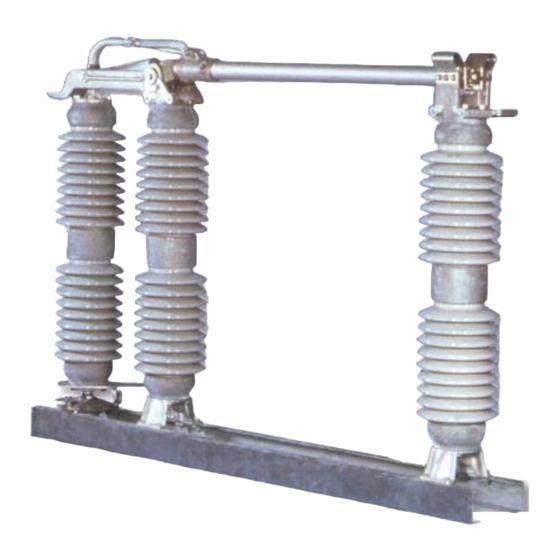
Summary of Contents for PASCOR ATLANTIC TTR6
- Page 1 IB-TTR6-B May 2012...
-
Page 2: Table Of Contents
Contents Subject Page Receiving and Handling ..........Installation and Adjustment Step 1. -
Page 3: Installation And Adjustment
However, it is recommended that each switch the transportation company and notify your pole be checked for alignment and proper Pascor Atlantic representative. adjustment after being mounted on the structure. HANDLING Rotor or Spacer Base... -
Page 4: Step 2-Assemble Insulators
Step 3—Insulator Stack Alignment Lower voltage switches 8.25 thru 72.5kV generally do not require insulator stack alignment. Where required, the insulator stacks of switches thru 242kV can be aligned using open-end shims or leveling screws and/or adjusting nuts (Fig. 1) if supplied (optional). •... -
Page 5: Step 5. Switch Blade Adjustment
Adjustable Clevis C onnecting Link Offset Bearing Rod R otor Bearing C oupling Operating Pipe F lexible Ground Strap Manual Worm-Gear Operator contact alignment. This alignment will be discussed later under blade entry (step 6). Fig. 5a Manual Worm Gear Operating Mechanism Step 5—Mount Switches Assemble the switches on the supporting give proper blade entry, the jaw insulator stack... - Page 6 P a g e...
- Page 7 Fig 9. Operating Handle Lock Plate Fig. 8 Geared Mechanism Also, Fig. 4 shows blade contact high on the right and low on the left. The reverse is also acceptable, high on the left and low on the right. It is common to have both situations on one three-pole switch.
-
Page 8: Step 7-Mount Offset Bearing
3” Bolt Circle Insulators have a multi-angle crank that permits 333 degrees of angular adjustment with a crank location every 9 degrees, which results in adjustments to within 4-1/2 degrees of desired position. 5” Bolt Circle Insulators have a multi-angle crank that permits 336 degrees of angular adjustment with a crank location every 12 degrees which results in adjustments to within 6... -
Page 9: Step 11-Install Pipe Splice And Guide Plate
the two piercing set screws on the handle clamp Step 11—Install Pipe Splice and Guide Plate until holes are punched into the pipe and When the structure height exceeds 23 feet, a continue until the screws are firmly seated. pipe splice and a guide plate are furnished Worm Gear Mechanism and should be installed as shown in Fig. -
Page 10: Step 14-Installation Of Corona Rings And Balls
horn makes contact with the rear surface connect aluminum-to-aluminum (corona-protected surface) of the corona ball. terminals: Note: Always check switch operation mechanism drawing for type of arcing horns supplied. 1. Clean all contact surfaces of conductors and fittings using a stiff wire brush to remove Step 14—Installation of Corona Rings and heavy oxide coatings until the aluminum Balls... -
Page 11: Maintenance
that the contacts be examined to see that they are aligned, clean, and have a firm uniform pressure. If the contacts are pitted, or burned to some MAINTENANCE extent, they should be removed and replaced. Under normal service conditions, the jaw WARNING contacts should be examined and maintained at least once a year, depending upon the type of... -
Page 12: Counterbalances
UPRIGHT TO VERTICAL In general, operating linkages require virtually no maintenance. However, in contaminated atmospheres of where operation under sleet WARNING conditions is common some lubrication at pivot When performing this procedure, use care points may be desirable. The grease used should because parts are in tension. -
Page 13: Bearings
5. Lower the blade to approximately a 15 degree angle 6. At or near this point, the counterbalance plunger can be connected to the proper point for vertical mounting. 7. Raise the blade to relieve pressure. 8. Remove the vise grip pliers 9. -
Page 14: Cranks
CRANKS the blade up from below and noting the lbs. at which the blade is lifted off the jaw stop, or by The two switch poles that are not connected to putting a wire loop around the blade and lifting the offset bearing normally use a single crank, it with the gauge and noting the lbs. -
Page 15: Renewal Parts
RENEWAL PARTS Refer to the switch nameplate when ordering renewal parts. The nameplate is attached to the base assembly of each switch pole. The same data is shown on the record engineering drawings. The master file at the factory is linked to the serial number on the nameplate. Renewal Parts Ordering Information Serial Number Switch Type...
Need help?
Do you have a question about the TTR6 and is the answer not in the manual?
Questions and answers