
Summary of Contents for aquilar aquitron AT-MGS-408
- Page 1 AquiTron AT-MGS-408 Gas Detection Controller I N S TA L L AT I O N & OPE RAT I O N I N ST R U CT I O N S...
-
Page 2: Table Of Contents
AT-MGS-408 User Manual Table of Contents Introduction ..........1 1.1. About this Manual ..................... 1 1.2. Conventions ........................ 1 1.2.1 Short Form Instructions........................1 1.2.2 Iconography ............................2 1.3. General Safety Statements ..................2 Product Description ........4 2.1. Product Overview ...................... 4 2.2. - Page 3 AT-MGS-408 User Manual 4.2.5 LCD Contrast ............................19 4.2.6 LED Brightness & Auto-dimming ....................... 19 4.2.7 Date/Time ............................. 20 4.2.8 Password Protection ........................... 20 4.2.9 Factory Reset............................21 4.2.10 Update Firmware ..........................21 4.3. Channel Summary and Setup ................... 22 4.3.1 Channel Setup Overview ........................
- Page 4 AT-MGS-408 User Manual Additional Information ....... 41 7.1. Disposing of Instrument ................... 41 7.2. Technical Specifications .................... 41 Parts and Accessories ........42 8.1. Part Numbers ......................42...
-
Page 5: Introduction
1. Introduction 1.1. About this Manual Thank you for investing in a Aquitron AT-MGS-408 Gas Detector Controller. To ensure operator safety and the proper use of the controller, please read the contents of this manual for important information on the operation and maintenance of the instrument. -
Page 6: Iconography
AT-MGS-408 User Manual 1.2.2 Iconography Alert Icon Description Imminently hazardous situation which, if not avoided, will DANGER result in death or serious injury. Potentially hazardous situation which, if not avoided, WARNING could result in death or serious injury. Potential electrical shock hazard which, if not avoided, WARNING could result in death or serious injury. - Page 7 CAUTION: In case of malfunction, DO NOT continue to use this equipment if there are any symptoms of malfunction or failure. In the case of such occurrence, de-energize the power supply and contact Aquilar on 01403 216100. CAUTION: Use ONLY the provided cable glands for electrical and...
-
Page 8: Product Description
AT-MGS-408 User Manual 2. Product Description 2.1. Product Overview The AT-MGS-408 Gas Detection Controller displays comprehensive and centralized information about the status of all connected gas detectors. A maximum of eight AquiTron gas detectors can be connected to the AT-MGS-408 via Modbus RTU. Compatible gas detectors are: •... -
Page 9: Intended Use
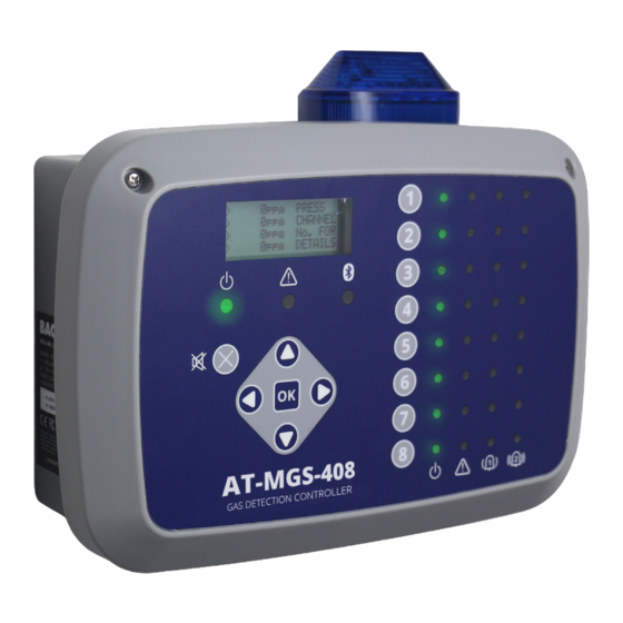
AT-MGS-408 User Manual include a date stamp of all high and low alarms as well as all faults. Figure 2-1 - AT-MGS-408 Gas Detection Controller with Optional External Beacon WARNING: This instrument is neither certified nor approved for operation in oxygen-enriched atmospheres. -
Page 10: Design Features
AT-MGS-408 User Manual 2.3. Design Features Power Options 100 - 240 VAC, 50/60 Hz, 80 W (max.) Provides power for 1 - 8 compatible AquiTron gas detectors Output/ RS485 Modbus RTU Master for Gas Detectors Communications Diagnostic / Status LEDs Controller (power, fault) Gas Detectors (power, fault, low alarm, high alarm) Outputs... -
Page 11: Components
AT-MGS-408 User Manual 2.4. Components Figure 2-2 - Component Layout DC, RELAY WIRING: 14-22 AWG RS-485, BEACON WIRING: 18-26 (2.08-0.37 mm ). Strip Length .25″ (6 AWG (0.83-0.13 mm ). Strip Length .20″ (5 mm). Torque: 31-35 in-oz mm). Torque: 31-35 in-oz (0.22-0.25 MAINS WIRING: 12-18 AWG Nm). -
Page 12: Communication Features
AT-MGS-408 User Manual Figure 2-1 - Front Panel Layout AT-MGS-408 Component Description LCD Display Power, Warning and Bluetooth indicator LEDs Alarm Mute Button Main Keypad | Arrow and OK keys Channel Keys Power, Fault, Low Alarm (1), High Alarm (2) LEDs for each sensor channel IMPORTANT: Bluetooth LED indicates when a downstream sensor has established a connection with the MGS-400 App. -
Page 13: Installation
Visually inspect the interior of the enclosure for loose wires or components that may have become dislodged during shipment. If damage is discovered, please contact a qualified repair technician or contact Aquilar Ltd. -
Page 14: Suitable / Appropriate Locations
AT-MGS-408 User Manual 3.3. Suitable / Appropriate Locations The AT-MGS-408 Gas Detection Controller should be centrally located in the facility (preferably outside of the mechanical room) and should be easily accessible for visual monitoring and servicing. This is the “split architecture design” for safety of the operator. Dirt, grease, and oils can adversely affect the operation of the controller. -
Page 15: Electrical Wiring
AT-MGS-408 User Manual 3.5. Electrical Wiring The controller enclosure features two M20 cable glands that are intended for power entry. If conduit is preferred, simply remove one of the M20 glands and install a suitable ½″ conduit adapter. Locate the AC power and Ground on the power input terminal block. Secure the incoming AC power neutral (white / blue), live (black / brown) and ground wires to the appropriate terminals, using a screwdriver on the press-to-release tabs. -
Page 16: Communications Connections
AT-MGS-408 User Manual 3.6. Communications Connections 3.6.1 AT-MGS-408 Gas Detection Controller Network The AT-MGS-408 Gas Detection Controller is connected to AT-MGS-410, 450, 460, 550 gas detectors using a shielded twisted pair instrument cable (Belden 3106A or equivalent). The maximum distance between the AT-MGS-408 and the furthest AquiTron gas sensor when using Modbus communications is 305M. -
Page 17: Integration With Building Management System
AT-MGS-408 User Manual 5. Connect the shield or drain wire to the “SH” connection point. 6. Locate the Modbus/RS-485 connectors in the AT-MGS-408 Gas Detection Controller. The left Modbus/RS-485 connector (labeled “Detectors”) is for down line “slave” devices (includes a dedicated shield position) and the right Modbus/RS-485 connector (labeled “BMS”) is used to connect to “master”... -
Page 18: Overview
AT-MGS-408 User Manual 4. Operation 4.1. Overview 4.1.1 Main Function Every five seconds the AT-MGS-408 Gas Detection Controller collects gas concentration and status information from each connected gas detector. Gas concentration appears on the LCD display and connection status, fault and alarm conditions are indicated by the LED matrix for each channel. -
Page 19: Controller Setup
AT-MGS-408 User Manual Some of the screens you will access will require data entry, such as the date/time setup or location description. These screens will appear with a character selected, as displayed below. Use the up / down Arrow keys to scroll through the characters provided for that character’s place. -
Page 20: Relay Setup
AT-MGS-408 User Manual how the controller has been wired. Main Menu CONTRLR CONFIG press OK, to access the setup parameters menu. Figure 4-6 - Setup Controller Configuration 4.2.2 Relay Setup To access the Relay setup menu: Main Menu CONTRLR CONFIG RELAYS press OK. ... -
Page 21: Audible/Visual (Av) Alarm Beacon
AT-MGS-408 User Manual 4.2.3 Audible / Visual (AV) Alarm Beacon The beacon, if installed, and the internal buzzer may be enabled to indicate an alarm condition. When enabled, the beacon will be energized, and the buzzer will beep, if either a low or high alarm condition exists. ... -
Page 22: Lcd Contrast
AT-MGS-408 User Manual 4.2.5 LCD Contrast From the LCD contrast setting screen, the contrast can be adjusted from 1-63, with 30 being the default. Main Menu CONTRLR CONFIG LCD CONTRAST press OK , to access the contrast menu. -
Page 23: Password Protection
AT-MGS-408 User Manual menu. Press the Up or Down arrows to select date/time increment to change, and then press OK. (The selected numeral will begin to flash.) Press the Up/Down arrows to change entry, Left/Right arrows to move cursor, press OK. -
Page 24: Factory Reset
AT-MGS-408 User Manual IMPORTANT: Make note of your password and save it. 4.2.9 Factory Reset Selecting FACTORY RESET will revert all user settings to their factory, out of box, defaults. A confirmation screen will ask the user to confirm their intent since user settings will be lost and you will need to re-configure each channel. -
Page 25: Channel Summary And Setup
AT-MGS-408 User Manual Main Menu CONTRLR CONFIG UPDATE FIRMWARE press OK, to perform a firmware update. Press press OK to proceed; X to exit. Figure 4-16 - Firmware Screen Figure 4-17 - Firmware Reset 4.3. Channel Summary and Setup Pressing a CH (X) key from the Channel Configuration screen will bring up a channel summary screen with detailed information collected from the gas detector assigned to that channel. -
Page 26: Channel Setup Overview
AT-MGS-408 User Manual 4.3.1 Channel Setup Overview Prior to setting channel parameters, the installer should verify and record the instrument type, node address and baud rate for each connected detector. All detectors must be set for the same baud rate, either 9600 (default) or 19200, and must have a unique node address. -
Page 27: X) Typ (Instrument Type)
AT-MGS-408 User Manual an detector without power. Setting the MON parameter to OFF will exclude the gas detector assigned to that channel from being scanned. If all channels have monitor parameters set to OFF, a system level fault will be triggered to indicate no detectors are being monitored. -
Page 28: Data Logging
AT-MGS-408 User Manual 4.4. Data Logging 4.4.1 Data Logging Overview With an SD card installed, the AT-MGS-408 will log concentration, units of measure, gas name, low or high alarm state, detector fault code and controller fault code, every 10 seconds. Log data is buffered for 10-minutes before writing to the SD card, so it is important to use the ‘SD EJECT’... - Page 29 AT-MGS-408 User Manual 4.4.3.1 SD EJECT Select this option prior to removing the SD card. This will write any buffered log data to the card and turn off logging. Logging will automatically resume when the SD card is re-installed. Main Menu DATA LOGGING SD EJECT press OK, to safely eject an SD card. 4.4.3.2 LOGGING(ON/OFF) Enable or disable data logging by setting this item to ON or OFF.
-
Page 30: Modbus
AT-MGS-408 User Manual 5. MODBUS 5.1. MODBUS Overview MODBUS RTU protocol is utilized both for down line detector communication and up line BMS communication. Communication parameters may be set from the MODBUS CONFIG menu. The AT-MGS-408 controller acts as a MODBUS master device on the detector side, and as a MODBUS slave device on the BMS side. -
Page 31: Slave Baud Rate
AT-MGS-408 User Manual 5.1.3 SLAVE BAUD RATE The AT-MGS-408 controller will us this baud rate to communicate with the upstream BMS or MODBUS master device, either 9600 (default) or 19200. Main Menu MODBUS CONFIG SLAVE BAUD press OK, to change the Slave BAUD: ... -
Page 32: Modbus Registers
AT-MGS-408 User Manual 5.2. MODBUS Registers Register Func Code 04 Item Group Notes Address (read input registers) 0=NOT MONITORED 30001 Sensor 1 is monitored flag Sensor 1 1=MONITORED 1=COM NORMAL, 30002 Sensor 1 communication status Sensor 1 2=COM FAIL Exception code from 30003 Sensor 1 modbus error code Sensor 1... - Page 33 AT-MGS-408 User Manual Register Func Code 04 Item Group Notes Address (read input registers) 1=ppm, 2=ppb, 30017 Sensor 1 Concentration Units Sensor 1 3=%VOL, 4=%LEL Power of 10 used on concentration, divide conc by 10^x for 30018 Sensor 1 Scale Factor Sensor 1 correct value (MGS-550 only)
- Page 34 AT-MGS-408 User Manual Register Func Code 04 Item Group Notes Address (read input registers) 30051- SENSOR 2 DATA GROUP Sensor 2 30100 (REPEAT OF SENSOR1) 300101- SENSOR 3 DATA GROUP Sensor 3 30150 (REPEAT OF SENSOR1) 30151- SENSOR 4 DATA GROUP Sensor 4 30200 (REPEAT OF SENSOR1)
- Page 35 AT-MGS-408 User Manual Register Func Code 04 Item Group Notes Address (read input registers) 31041 Sensor 5 Fault code Sensor 5 31042 Sensor 6 Fault code (high bytes) Sensor 6 31043 Sensor 6 Fault code Sensor 6 Sensor 7 Fault code (high bytes) 31044 Sensor 7 31045...
- Page 36 AT-MGS-408 User Manual Register Func Code 04 Item Group Notes Address (read input registers) Relay 3 Contact Behavior / Controller- 40015 0=normal 1=Failsafe Failsafe related 40016 24V supply voltage x 100 Diagnostics 2400=24.00V 24V supply output to sensors 2400=24.00V 40017 Diagnostics voltage x 100 300=3.0V...
- Page 37 AT-MGS-408 User Manual Controller- 0=Disabled 1=enabled 40025 Fault Latching Enabled related...
- Page 38 AT-MGS-408 User Manual Register Func Code 02 Item Group Address (read input status) 10001 Sensor 1 Low Alarm Flag (0 or 1 = alarm) Sensor 1 10002 Sensor 2 Low Alarm Flag (0 or 1 = alarm) Sensor 2 10003 Sensor 3 Low Alarm Flag (0 or 1 = alarm) Sensor 3 10004...
- Page 39 AT-MGS-408 User Manual Register Func Code 02 Item Group Address (read input status) 10131 Sensor 3 enabled flag (0=disabled 1=enabled) Sensor 3 10132 Sensor 4 enabled flag (0=disabled 1=enabled) Sensor 4 10133 Sensor 5 enabled flag (0=disabled 1=enabled) Sensor 5 10134 Sensor 6 enabled flag (0=disabled 1=enabled) Sensor 6...
-
Page 40: Diagnostics & Troubleshooting
AT-MGS-408 User Manual 6. Diagnostics & Troubleshooting 6.1. Diagnostic Menu From the diagnostic menu the user can review and clear current and historical faults, view power supply voltages, and watch live Modbus traffic for both master, slave and Bluetooth connections. The diagnostic menu appears on the second page of the main menu. -
Page 41: Display Last Fault
AT-MGS-408 User Manual 6.1.2 DISPLAY LAST FAULT Displays historical fault code and listing. Intermittent fault conditions can be reviewed here. Main Menu DIAGNOSTICS LAST FAULT press OK, to access review fault conditions. Use the Up/Down arrows to select a fault descriptor, then press OK for more detailed information about the fault and possible remedies. -
Page 42: Modbus Slave
AT-MGS-408 User Manual 6.1.7 MODBUS SLAVE Displays the live Modbus traffic for the BMS connection. Use when troubleshooting communication problems with upstream master devices. Main Menu DIAGNOSTICS MODBUS SLAVE press OK, to clear the screen and view the next query and response. -
Page 43: Fault Codes
AT-MGS-408 User Manual 6.2. FAULT CODES Code Critical Fault Possible Causes Remedy CHASSIS Chassis temperature outside Reduce ambient temperature or check 0001 TEMP HI the range of -20 to 60° for power supply malfunction. RS485 MSTR Buffer overflow Disable all but one channel, use MODBUS 0002 BUFR communicating with detectors... -
Page 44: System Tests
AT-MGS-408 User Manual Code Critical Fault Possible Causes Remedy Reset or reboot controller, if fault 4000 CPU ERROR Microcontroller malfunction persist, consult factory. EEPROM 8000 EEPROM malfunction Consult factory. ERROR 6.3. SYSTEM TESTS Main Menu SYSTEM TESTS press OK, to access the system tests menu. To facilitate installation and troubleshooting the following test are available from the SYSTEM TEST menu. - Page 45 AT-MGS-408 User Manual 7. Additional Information 7.1. Disposing of Instrument EU-wide regulations governing the disposal of electrical and electronic appliances which have been defined in the EU Directive 2012/19/EU and in national laws have been effective since August 2012 and apply to this device. Common household appliances can be disposed of using special collecting and recycling facilities.
- Page 46 AT-MGS-408 User Manual 8. Parts and Accessories 8.1. Part Numbers AT-MGS-408 Configurations Part # Description 40800 AT-MGS-408 gas detection controller, 8 channels AT-MGS-408 Accessories Part # Description AT-MGS-408-SR - Optional sounder/beacon, mounts directly 40802 onto AT-MGS-408, red lens AT-MGS-408-SG - Optional sounder/beacon, mounts directly 40803 onto AT-MGS-408, green lens AT-MGS-408-SB - Optional sounder/beacon, mounts directly...
- Page 47 Unit 30, Lawson Hunt Industrial Park, Broadbridge Heath, Horsham, West Sussex, RH12 3JR +44 (0) 1403 216100 info@aquilar.co.uk www.aquilar.co.uk...
Need help?
Do you have a question about the aquitron AT-MGS-408 and is the answer not in the manual?
Questions and answers