
Summary of Contents for MDS E-PGM+
- Page 1 Microcontroller Development System E-PGM+ / E-PGM Serial / E-GANG Manual 2021. 02. 15 ABOV Semiconductor MDS Team...
-
Page 2: Table Of Contents
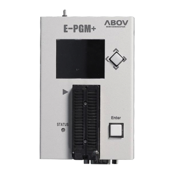
Contents E-PGM+ / E-PGM Serial / E-GANG specification How to update the E-PGM+ / E-PGM Serial / E-GANG Programming a microcontroller Pin name of Socket and ISP connector Device connection Handler connection Trouble shooting Useful Info. For 97F1104S/1204S/1316S(E-PGM+ Only) 10. Compare : E-PGM+ vs E-PGM Serial 11. - Page 3 1-1. E-PGM+ / E-PGM Serial specification • Product name : E-PGM+ / E-PGM Serial • Standalone programmer • No need to connect PC • VDD is supplied to devices • Programming Power Output • VDD : 2.5V ~ 5.5V, 200mA •...
- Page 4 1-2. E-GANG4 / E-GANG6 specification • E-PGM+ S/W support E-GANG(4/6). • Four or Six pieces of E-PGM+ included • Power control board is included. USB hub is included. • When main power is on, each E-PGM+ is sequentially power on. •...
-
Page 5: How To Update The E-Pgm+ / E-Pgm Serial / E-Gang
2. How to update E-PGM+ / E-PGM Serial / E-GANG • The PC(personal computer) is not needed any more after completing the update. • Please check the USB device driver installed. • The USB device driver is located at ABOV homepage. Programmer : E-PGM+, E-GANG4, E-GANG6, E-PGM Serial 1. -
Page 6: Programming A Microcontroller
3. Programming a microcontroller The PC(personal computer) is not needed any more after completing the update. * Press the Joy-button to read. This mode does not update the E-PGM+ with the user-hex data. For displaying the checksum and option-value. Read Check the device ,code checksum and device-options Press the Enter-button. -
Page 7: Pin Name Of Socket And Isp Connector
4. Pin name of Socket and ISP connector Signal Socket ISP connector CLOCK DATA Run Flag 1. MCU UART-RX 2. VDD 3. MCU UART-TX 4. GND 5. Run Flag or Boot Pin or ACK 6. Serial Clock 7. GND 8. Serial Data 9. -
Page 8: Device Connection
5-1. Device connections - AC33M6128/8128, AC33M3064/4064 UART Warning The E-PGM+ supplies VDD with the target board. * Do not turn on a user target board. * The E-PGM+ can be damaged when the power of the target B/D is on. 1. - Page 9 5-2. Device connections – MC80F7708 UART ISP UART Warning The E-PGM+ supplies VDD with the target board. * Do not turn on a user target board. * The E-PGM+ can be damaged when the power of the target B/D is on. 1.
- Page 10 5-3. Device connections – 32bit MCU SWD interface SWD(Serial Wire Debug) Warning The E-PGM+ supplies VDD with the target board. * Do not turn on a user target board. * The E-PGM+ can be damaged when the power of the target B/D is on. 1.
- Page 11 5-4. Device connections - AC33M6128/8128-SPI, AC33M3064/4064-SPI Warning The E-PGM+ supplies VDD with the target board. * Do not turn on a user target board. * The E-PGM+ can be damaged when the power of the target B/D is on.
- Page 12 6-1. E-PGM+ / E-PGM Serial handler connection • 3.3V Power output • Output → Good, Fail indicate signal (active “L”) • Input → Start Key (active “L”) Handler Cable connector +3.3V MOLEX Part Number: 50-37-5023 (SD-5264-05) 2.50mm Pitch SPOX™ Wire-to-Board Crimp Housing, Friction Lock, 2 Circuits Start Good Fail...
- Page 13 6-2. E-GANG4 / E-GANG6 handler connection • Internal isolator • Used the Handler 5V(3.3V) Power • Output → Good, Fail indicate signal (active “L”) • Input → Start Key (active “L”) +5V (3.3V)
-
Page 14: Trouble Shooting
7-1. Trouble shooting When executing E-PGM+.exe, following error message is occurred. The error reason: WDAPI1010.DLL is not at C\windows folder. If you setup device driver, it can copy at C\windows folder. Korean English... - Page 15 7-2. Trouble shooting When executing E-PGM+.exe, the firmware folder and E-PGM.txt file are located at same folder. If you want to execute at desktop, you need to use “ desktop shortcut”. No Firmware folder E_PGM.txt is not found.
- Page 16 7-3. Trouble shooting : USB driver 1. Close E-PGM+ S/W 2. Disconnect USB line 3. Run USB_driver_unistall.exe (Version 1.7) 4. Delete C:\Windows\System32\drivers\windrvr6.sys 5. Copy windrvr6.sys which is in the driver install files 64 bit : Copy x64\windrvr6.sys to C:\Windows\System32\drivers\ 32 bit : Copy x32\windrvr6.sys to C:\Windows\System32\drivers\ 6.
- Page 17 8-1. Info. : Error message at writing Error message Error and reason No DPID Related with ARM devices VDD/GND/SWDCLK/SWDATA are not connected. No device-ID Vdd/Gnd and signals are not connected. Read-ID = 0xxxxx Wrong device is selected. Power Check - Supplied Vdd/Vpp voltage not correct Vdd : xx or Vpp : xx - On board writing, target B/D spend lots of current and drop voltage - On board writing, target B/D is short between Vdd and GND...
- Page 18 8-1. Info. : Error message at writing Error message Error and reason Debug Power The reset ic in the board is in reset state. Request Fail If tool-Vdd is lower than the Vdd of reset IC. Ex) Tool Vdd : 3.3V, Reset IC : 4.2V As the default voltage is 3.3V, need to change Vdd from 3.3V to 4.5V CPU Reset Device is in reset state.
- Page 19 8-2. Info. : ISP Connections Note1) DSCL DSCL/CLK/SWD_CLK Note1) DSDA DSDA/DATA/SWD_DATA Writer user mode user reset • circuit switch RST/VPP VPP/Reset ISP mode Writer User Application Board Note1) If other signals affect the communication in ISP mode, disconnect them with pins by using jumper or switch.
- Page 20 8-3. Info. : Connectors Power switch Connect USB mini type cable. Power DC 15V Enter Key Connector. To connect with the auto-handler 1. MCU RX 2. VDD 3. MCU TX 4. GND 5. Run Flag or Boot Pin 6. Serial Clock 7.
- Page 21 8-4. Info. : Structure of a HPO file A HPO file opened by a text editor Option Info. Device Name Structure of a HPO file Device Name : @DeviceName Option : Ooption info Tool VDD : VDD X.X Hex code...
- Page 22 8-5. Info. : Run E-PGM+ with loading a HPO file E-PGM+.exe –hpo filename.HPO example => C:\E-PGM+.exe -hpo test.HPO...
- Page 23 8-6. Info. : PC mode S/W (E-PGM+ only) For A31R118 only E-PGM+ update S/W should be closed before running PC mode S/W. Set Gang ID Open the case and locate the switch. ID is start from 0. Connect PC with tool Set Serial ID info, generate 1,000,000 id, enable Program with serial id button Program Code &...
- Page 24 8-7. Info. : Important displayed information After updating firmware and user-hex code, it is required to check following items. Device Name User hex-code checksum Device Option values...
- Page 25 8-8. Info. : E-PGM+ / E-PGM Serial : multiple operation(Gang mode) • Short Gnd and start signals. • Multiple writing at pressing a write button.
- Page 26 9-1 : For MC97F1104S/1204S/1316S (1/3) Only for E-PGM+ For MC97F1204S, MC97F1104S, MC97F1316S, and PCB Version V5.5. The level of Vpp is 17V. The SW3 switch is for Vpp level. If Step-up is selected, the max. Vpp level is 19.0V. If Ext. is selected, the max. Vpp level is 15.0V. If you use above chips, the SW3 switch is set as Step-up.
- Page 27 9-2 : For MC97F1104S/1204S/1316S (2/3) Only for E-PGM+ Note1) DSCL DSCL 97F1204S Note1) DSDA DSDA 97F1316S Writer user mode user reset • circuit switch RST/VPP Note2) 17.0V 200 ISP mode Writer User Application Board Note1) If other signals affect the communication in ISP mode, disconnect them with pins(DSDA/DSCL) by using jumper or switch.
- Page 28 9-3 : For MC97F1104S/1204S/1316S(3/3) Only for E-PGM+ To remove the 200 Ohm resistor in the board, Please insert the resistor in the Vpp line.
- Page 29 10. Comparison : E-PGM+ vs E-PGM Serial E-PGM+ E-PGM Serial Socket writing No 40pin Dip socket Supported All devices 94/95/96/97XXXX series (Not support 97F1104S/1204S/1316S) Devices All 32 bit MCU Buffer Size 1MByte 8MByte Read Button Joystick button Simple push button Support UART Barcode reader Built-in protection circuits...
- Page 30 11. Set VDD You can change VDD value for following reasons. ◆ On ISP(In System Programming), the detect voltage of RESET IC on board must be lower than VDD of E-PGM. • If the reset voltage is 4.2V and “Set VDD” is 3.3V, Programming may be failed because the device of board is on reset. ◆...
-
Page 31: Device Password
12. Device Password Device : A96G166, A96T418 Lock password After writing hex code write, password lock is enabled. The 12 byte hex-value for password are programmed. Unlock password After checking device-id, if password is enabled, The 12 byte hex-value for password are compared. ... -
Page 32: Set Serial Id
13. Set Serial ID 1. Start addr : Start address of serial -ID 2. Length : Length of serial-id, 4 byte or 8 byte 3. Value : ID value - Little endian type - 0x1F000 : 08 07 06 05 04 03 02 01 4. -
Page 33: Set Limit Number Of Write
14. Set limit Number of Write 1. Enable Limit Number of Write 2. Available limit number : 1 ~ 1,000,000 3. Limit number is decreased per write. - Page 34 14. E-PGM Tool Self Check 1. 툴에 연결된 디바이스를 제거함. ( Remove a device in a tool) 2. E-PGM+.exe 실행 ( Run E-PGM+.exe) 3. Device select <SELF_TEST>E-PGM+ 4. Update 실행(Press update-button) 5. 업데이트 완료 후 TEST 실행 (Run test after update) - E-PGM+는...
- Page 35 15. OFF LINE : Get code-checksum To get a checksum without connection with PC. 1. Press Save HPO 2. Select tool-type =>E-PGM + : E-PGM+, E-GANG5/6 =>E-PGM Serial : E-PGM Serial 3. Device select 4. Load a hex-file 5. Check checksum...
- Page 36 16. Tool Option : Erase Data Flash If you select the Erase Data Flash, Data Flash is erased during write-sequence. Supported devices : A33G527, A33G526...
Need help?
Do you have a question about the E-PGM+ and is the answer not in the manual?
Questions and answers