Table of Contents
Advertisement
Quick Links
Advertisement
Table of Contents

Summary of Contents for TeleEye NF620
- Page 1 User Manual NF620 Before using the product, please read this manual carefully...
- Page 2 Tele Eye is a trademark of Signal Communications Limited and is registered in China, Hong Kong, US and other countries. TeleEye's products are sold under the brand name of CAMERIO in Australia, Japan, Korea, New Zealand, Taiwan and Argentina. CAMERIO is a trademark of Signal Communications Limited and is registered in Australia, Japan, Korea, New Zealand, Taiwan and Argentina.
-
Page 3: Table Of Contents
LANK ANEL 2.4 T ............13 FUNCTION 3. INSTALLATION..............14 3.1 CONNECTING WITH A MULTIPLEXER..... 14 3.2 UPDATING SYSTEM SOFTWARE ......15 3.3 NF620 SD ......17 CARD ROUBLESHOOTING 4. Network Configuration ............ 18 4.1 C ........... 18 ABLE ONNECTIONS 4.1.1 Connect to a computer ......... - Page 4 5.2.4 The Image Viewer ........81 6. ADVANCED OPERATION ..........82 7. SPECIFICATIONS............. 86 APPENDIX 1. –NF620 UPnP How To ........87 APPENDIX 2. –The ARP function........98 APPENDIX 3. –Register as a DDNS member ....100 APPENDIX 4. –FAQ ............104...
-
Page 5: Safety Precautions
SAFETY PRECAUTIONS All the following safety and operational instructions to prevent harm or injury to the operator(s) or other persons should be read carefully before the unit is activated. WARNING To prevent fire or shock hazard, avoid exposing this unit to rain or moisture. Do not block ventilation openings. -
Page 6: Product Features
USB interface which helps you to very easily get an IP address to open the IE browser: just type in your IP address to the browser and you can access your NF620. The device can hopefully provide the advanced motion detection function to improve your network surveillance with both the powerful and enhanced multi-zone and multi-sensitivity modes of detection. -
Page 7: Product Features
◆ Position a camera any place you want–No PC required for operation. ◆ Supports pre-alarm & post-alarm functions. ◆ Supports the MDIX protocol. Recognizes both the normal and the crossover cables, either of which can connect up with a NF620. -
Page 8: Technical Specifications
1.3 Technical Specifications General: ‧ Built -in Web Server and network interface. You don’t need a PC to operate. Installation: ‧ Fast and simple installation – connect to your network and assign an IP address within a minute. The null modem cable enclosed helps you to set up without a network. Camera: ‧... - Page 9 Supported Protocols: ‧TCP/IP, DHCP, HTTP, SMTP, SNTP, DDNS, DNS Security: ‧ Password protection available, unless exposure is preferred. Connections: ‧ RJ 45 twisted pa ir cable, 10/100 Mbit Ethernet network connection. ‧ Modem connection: RS -232 modem connector for dial-up use. Supports most V90 modems.
-
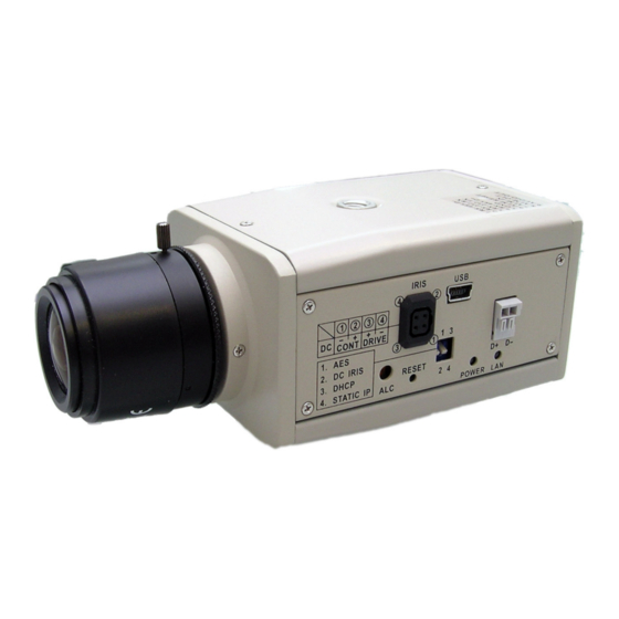
Page 10: Description Of The Front/Rear View
VIDEO DC5V 1. MICROPHONE: The NF620 has an additional audio function. The device has a microphone built into its front panel which records sound. 2. ALARM I/O & RS-232 Port: The RS-232 communication port functions as a connector to an external control device. This port includes ALARM OUT, GROUND, ALARM IN, and ALARM RECOVER for connecting with external devices. -
Page 11: Port & Alarm I/O
2.2 RS-232 Port & ALARM I/O 1 2 3 4 5 RS-485 D- RX: This pin is one of the RS-232 pins. It connects with the TX pin of another device. TX: This pin is one of the RS-232 pins. It connects with the RX pin of another device. Please refer to the note below on the standard RS-232 9 Pin Cable with Pin 2 and Pin 3 exchanged;... -
Page 12: Flank Panel
RS-485 Port: The RS-485 communication ports function as connectors when two or more units are serially connected to an external control device. 5pin MINI USB Port: The user can use a USB device cable to connect the NF620 to the USB port on the PC. -
Page 13: The Usb Function
SD card. In another words, if the user connects the NF620 with an SD card and the PC via the USB connector, the NF620 can be used as a normal card reader. -
Page 14: Installation
Please follow the instructions and the diagram below to set up the system. NOTE: The NF620 is linked by its Video Out connection via a BNC connector to a monitor's Video In connection. If this connection is there, you can see some information on the monitor screen, such as the NF620 factory default Static IP address(192.168.1.168). -
Page 15: Updating System Software
PLEASE", please write down the error messages shown on the screen and inform your technical support, while ignoring the following steps. 10. Power off the NF620 when this update process is finished, then remove the SD card from the NF620. - Page 16 4; otherwise, please inform your technical support. 5. In step 10, if the SD card is not removed and the NF620 does not get online as well, the updating process must be repeated again after rebooting the NF620.
-
Page 17: Nf620 Sd Card Troubleshooting
1. Check if the SD card position is correct or not. Please refer to the manual for the related information. 2. After powering the NF620 on, correctly insert the SD card, and a little icon of "SD" will show up in the upper-right corner of the monitor screen. If not, it means the device detection has failed. -
Page 18: Network Configuration
4. Network Configuration 4.1 Cable Connections Please follow the instructions below to connect your NF620 to a computer or a network and to choose a proper RJ-45 cable configuration for connections. Physical specifications of the RJ-45 cable for Ethernet Wire Type Cat. -
Page 19: Connect To A Lan Hub (Intranet)
4.1.2 Connect to a LAN Hub (INTRANET) The RJ-45 PIN configuration for connecting with a LAN Hub is shown below. TO PC NETWORK CARD NF620 LAN CAMERA RJ-45 uplink... -
Page 20: Configure Your Nf620 Network Settings
GATEWAY: 0.0.0.0 NOTE: When only one unit of the NF620 is connected to a computer or LAN, you can freely assign an IP address for the NF620. For example, there is a range of NF620 IP addresses from 192.168.1.1 to 192.168.1.255. You can pick one for use from the range of the IP. - Page 21 If the connected network is identified as Class B, the first two sets of numbers of the NF620 IP address must be the same as the network address. If you have any questions regarding these settings, please...
-
Page 22: Tcp/Ip Communication Software
4.3 TCP/IP Communication Software Follow the procedure below to install the TCP/IP communication program in your computer. Click the Start menu from your computer, and point to the Settings/Control Panel. Double click the Network icon to enter the windows. - Page 23 Click the Configuration tag, and check if the TCP/IP is included among the network components list. If the TCP/IP is included, please process section 4.5. If it is not included, please follow section 4.4 to install the TCP/IP.
-
Page 24: Tcp/Ip Installation
4.4 TCP/IP Installation During the installation, you will be requested to insert the Windows CD-ROM. After installation, the PC may be restarted. -
Page 25: Tcp/Ip Configuration Setting
PC. This IP address must be different from other network IP devices but in the same class type. NOTE: The IP address of a NF620 in a network must be unique to itself as opposed to those of the other chosen PCs, but in the same class type. -
Page 26: Connection Testing
With the previous settings, follow the instructions below to ensure whether you have established the connection successfully. Click Start Programs MS-DOS Prompt Type in ping 192.168.1.168, then enter. (See the sample screen below). ** This IP is the NF620 IP address that is assigned for the connected NF620 in step2. - Page 27 Please re-check all the hardware and software installations by repeating steps 1 to 5. If you still can’t establish the connection after rechecking, please contact your dealer. NF620 If you receive a response as in the sample screen below, you have successfully made the connection.
-
Page 28: Operating Instructions For Image Software And Network
Two choices of software are available for linking with the NF620: (1) the Microsoft Internet Explorer; and (2) the NF620 VIEWER, a network browser in a PC which provides the functions of monitoring remote zones or watching recorded data through the TCP/IP protocol. The details are listed as follows. -
Page 29: Microsoft Internet Explorer
NF620. Click the URL block at the top of the window. Enter the URL address of the NF620 into the URL block and press the “Enter” button to enter the home page. Scroll to the bottom of the page, with its five icons, "Image", "Network", "System", "Application"... - Page 30 Browsing images from the NF620 The images from the NF620 will be displayed on the home page while going online with the NF620. Some buttons of the home page are provided for further setting. In MJPEG mode or in MPEG4 mode, there are different display formats of its home page.
-
Page 31: Change Image Setting
5.1.2 Change Image Setting Please follow the steps below to change the image setting through the network if necessary. 1. Click the Image button on the home page to enter the image-setting page. Image setting page of MJPEG mode Image setting page of MPEG4 mode 2. - Page 32 Viewer type: Click to choose the viewer type of the “ActiveX” or “JAVA Applet” mode. Submit: Click to submit the new image setting to the NF620. Default: Click this button to install the default settings in all the entries for image parameters...
-
Page 33: Change The Network Setting
5.1.3 Change the Network Setting Please follow the steps below to change the network setting through the network if necessary. Set the network options and IP address. Click the Network button in the home page to enter the Network page. The accessible networks here are the “FTP”... - Page 34 Description of function keys: IP Address: Enter the 4-byte IP Address in the appropriate blank space (the value in each box may be anywhere between 0 and 255). Every NF620 has to own an IP address to be identified on the network.
- Page 35 Password: Type in the FTP login password in the attached blank space (if the space is blank, warning messages will show up). Upload Path: Enter the upload path while doing the FTP. Submit: Click to submit the new FTP setting to the NF620.
- Page 36 Click the Home button to return to the home page. Description of function keys: SMTP Server: Enter the SMTP server DOMAIN NAME in the given blank space. Email Address: The recipient’s e-mail address. Submit: Click to submit the new SMTP setting to the NF620.
- Page 37 Time Zone: As we know, the globe is divided into various time zones. The user must enter his/her time zone. If this is not done, the time given by the unit may be incorrect. Submit: Click to submit the new SNTP setting to the NF620.
- Page 38 Change the Network Setting — DDNS. The “Network” page has, on its upper left, the “DDNS” icon. Please follow the steps below to change the DDNS setting through the network if necessary. Click the DDNS button at upper left above to enter the “DDNS Setting” page. Click “Enable DDNS Function”...
- Page 39 Description of function keys: Enable DDNS Function: Checkmark to activate the function. DDNS Type: Click to open the list of three DDNS modes to choose from: “DynDNS”, “hn”, and “adsldns”. Click the “Apply” button and connect this website automatically and enter it. Type in your dynamic IP Address and Email Address.
- Page 40 Change the Network Setting — PPPoE. The “Network” page has, on its upper left, the “PPPoE” icon. Please follow the steps below to change the PPPoE setting through the network if necessary. Click the PPPoE button at upper left above to enter the “PPPoE Setting” page. Click the “PPPoE mode”...
-
Page 41: Change The System Setting
4. Click the Home button to return to the home page. Description of function keys: The Local Time: Shows the current date and time of the NF620. Set Manually: Manually sets the date and time of the NF620. Synchronize With Computer Time: Synchronizes with the linking computer. - Page 42 Change the System Setting — Timestamp. Please follow the steps below to change/add the timestamp through the network if necessary. 1. Click the Timestamp button on the left side of the “System - Date and Time” page to enter the “System - Timestamp”...
- Page 43 Password: Enter the new password of the user’s name above. Confirm: Type in the password again for verification. Authority: Choose an authority option of the user’s name from: Admin, Operator, and Viewer. Submit: Click to submit the new setting to the NF620.
- Page 44 Change the System Setting — Digital I/O. Please follow the steps below to change the Digital I/O through the network if necessary. Click the Digital I/O button on the left side of the “System - Date and Time” page to enter the “System –...
- Page 45 Change the System Setting — Audio Mechanism. Please follow the steps below to change the Audio Mechanism through the network if necessary. Click the Audio Mechanism button on the left side of the “System - Date and Time” page to enter the “System –Audio Mechanism Setting”...
- Page 46 View the Event Logs. Please follow the steps below to view events through the network if necessary. Click the button on the upper left above to enter the “Event Log” page. Choose one of the three buttons shown on the page to view an event when necessary. The three buttons are titled “First Page”, “Previous 20”, and “Next 20”.
-
Page 47: Change The Application Setting
5.1.5 Change the Application Setting Please follow the steps below to change the application setting through the network if necessary. Change the Application Setting — FTP Application Setting (MJPEG mode only). Please follow the steps below to change the FTP setting via the network if necessary to upload recording data live. - Page 48 Change the Application Setting — SD Card Application Setting. Please follow the steps below to change the SD CARD setting via the network if necessary to upload recording data live. Click the SD card button on the top left to enter the “SD Card Application Setting” page. SD Card setting page of MJPEG mode SD Card setting page of MPEG4 mode You have an option as to which SD - card storage format to use, the MJPEG (MJPEG mode only)
- Page 49 Change the Application Setting —SMTP Application Setting (MJPEG mode only). Please follow the steps below to change the SMTP setting via the network if necessary. Click the SMTP button on the left side to enter the “SMTP Application Setting” page. Enter the attached file number as and when necessary.
- Page 50 Change language Please follow the steps to change the language setting via network if necessary. Click the box to select the language. λ Click the Submit buttom to submit the new language setting,...
- Page 51 Change the Application Setting —Record Application Enable Setting. Please follow the steps below to change the setting via the network if necessary. Click the Enable Record button on the left side of the record to enter the “Record Application Enable Setting” page. Record setting page of MJPEG mode Record setting page of MPEG4 mode Click “Enable Record –...
- Page 52 Vary any of the schedules of the recording setting if necessary (please refer to the above description). Chart: Schedule list. Submit: Click to submit the new setting to the NF620. Remove All Schedules: Click to clear out all the data of the schedule setting.
- Page 53 Change the Application Setting — Alarm Application Enable Setting. Please follow the steps below to change the setting via the network if necessary. Click the Enable Alarm button on the left side of the record to enter the “Alarm Application Enable Setting”...
- Page 54 Save: Click to save the motion detection range. Motion Detection: This option enables / disables the motion detection function. Sensitivity Level: Selects any one of the given options for the setup signal level. Submit: Click to submit the new setting to the NF620.
-
Page 55: Change The Sd Card Setting
5.1.6 Change the SD card Setting Please follow the steps below to change the SD card setting through the network if necessary. Change the SD card Setting — FILELIST of MEMORY CARD. Please follow the steps below to change the setting via the network if necessary. Click the “SD card”... -
Page 56: Change The Pan/Tilt Setting
5.1.7 Change the Pan/Tilt setting Click the Pan/Tilt button on the home page to open the Speed Dome Controller. Click “Configure” to enter to the RS232 and RS485 setting pages. RS232 Setting: Description of function keys: Baud rate: Eight different speeds can be used: 2400 baud per second, 4800 baud, 9600 baud, 19200 baud, 28800 baud, 38400 baud, 57600 baud and 115200 baud. - Page 57 RS485 Setting: Description of function keys: Baud rate: Eight different speeds can be used: 2400 baud per second, 4800 baud, 9600 baud, 19200 baud, 28800 baud, 38400 baud, 57600 baud and 115200 baud. Type: Choose one of the types. Device ID: You have the option of using an ID code (any number between 1 and 255). Raw format: Set to transmit the ASCII codes.
- Page 58 Select the connecting port. The RS-232 communication port functions as a connector to an external control device. The RS-485 communication ports function as connectors when two or more units are serially connected to an external control device. Upon the buttons being clicked, a camera will move one short step only in any of the four designated directions.
-
Page 59: Pppoe & Ddns
255) → Click the mask and the mask input, namely “255. 255. 255. 0” (a fixed formula) → Click “OK” → Click “OK”. Desktop → Choose IE browser → Type in the NF620 IP address in the URL (check step # 2 above) → Enter → NF620 images will appear. - Page 60 PPPoE settings and step 3 above) → You can see the NF620 images. DDNS settings Check your NF620’s IP address ( Scan IP software or monitor ) → open your IE browser → Use the address to connect to the NF620 or view the images → Choose the network →...
-
Page 61: The Nf62S
5.2.1 Introduction to NF62S The NF62S allows you to access many units of the NF620 from a remote desktop or a laptop in a TCP/IP networking environment. It can perform the following functions. View live images from the NF620. - Page 62 3. After the installation is complete, pop up the START menu from your computer, and point to Program Files\TeleEye\TeleEye NF62S to open up the program selection page as shown below. Click the NF62S tag to start the NF62S program.
- Page 63 4 Go to http://www.TeleEye.com login in as customer, and choose Support > Product Registration in Menu...
- Page 64 7. After the installation is complete, click the START menu from your computer, and point to Program Files\TeleEye\TeleEye NF62S to start the NF62S program. NOTE: Please make sure the TCP/IP communication software has been properly set and configured in your computer.
-
Page 65: Nf62S
Click the “Cancel” button and exit the login of the Network Viewer. View the NF620 video from a remote PC Follow the instructions below to use the NF62S to browse a NF620 video from a remote location. Upon entering the NF62S, a connection box will appear as follows. - Page 66 (1) Click the Auto-Search button at the bottom of the "Connect NF620 Wizard" page to discover the connection of the NF620 - type device in the LAN. Instantly the "Search NF620 " page will appear. Click the device of your choice and click "Select" at the bottom of the page to access the "Connect NF620 Wizard"...
- Page 67 After finishing the setting of the Device Recording, please click the "Finish" button to establish the connection between the device and the computer. Click the devise title to begin viewing images with this camera from the Device List. NOTE: To add more connections or units to the NF620, please repeat the above instructions.
- Page 68 Live Monitor Once the connection has been established, click the button to enter the Live Monitor window. (See the sample screen below.) On the left side of the window is the connected device that has been arranged when you established the connection. The Live Monitor icon.
- Page 69 The Full Screen button: Click this button to show the full screen for surveillance. If you want to return to the previous mode, please click the Normal Screen button. Motion on/ Alarm on: The warning icons. Motion-on icon: When there is a detection of motion in any channel, it will display this icon in the right upper corner of that channel to warn the user.
- Page 70 Playback Viewer Press the button to enter the Playback Viewer setting page. The Playback Viewer icon. The display area. Click to choose the Recording List Live Event Message The alarm events which were recorded will be marked in pink color. Click to refresh the recording list.
- Page 71 NOTE: To view the starting point of an alarm which was recorded, please (1) select the recorded event and (2) click the icon, then (3) the starting point will show on the display area. Move to left/right area. Recorded video list box. This box allows you to access all recorded video, which are stored in the HDD of the connected devices.
- Page 72 Capture / Print: Provides the image capturing and printing functions. Play Rate: During play mode, please use the scroll bar to control the show speed. Shows the device title. This allows you to search a recorded video kept in the HDD of the device. Enter the MONTH /DAY /YEAR /HOUR /MINUTE you wish to search and click to proceed.
- Page 73 “OK” to delete the group. Add a new camera. For mode details please refer to section 5.2.3. Remove a camera. Click this button and select the group name and NF620, then “OK” to delete the device. To edit camera. Please select a device then click this button to edit the device.
- Page 74 1. Device Setting page 2. Image Setting page NOTE: The NF62S software connects the Internet to a NF620. There may be a problem if the bandwidth is not enough, in which case the speed rate of the image transmissions may become too low.
- Page 75 NOTE: Please remember to click the “Apply” button to save the settings. Provides four pages of setting: the Global Settings, the Recording Settings, the Recording Scheduler and the Authority Setup. Global Settings (1) Monitor setup: Sets the date/time mode, display mode and control the CPU use percentage on five levels.
- Page 76 Recording Scheduler (1) Choose one of the devices to set its recording schedule. (2) Select the period: Click to set to record only once or record every day. (3) Select the recording time: Sets the periods of time in recording. Select the Begin time and the End time then the time markers will display above.
- Page 77 Erase the selected period schedule. You can also use the right mouse button to cancel the period. (4) Select the recording mode. (5) Press to show the scheduled recording list. (6) Set the secondary schedule: Activate or inactivate the other recording modes besides the primary schedule. (7) Option buttons: Undo: Undo the latest changes.
- Page 78 The web page (please refer to section 5.1 for more details): Device information: The user can read a camera’s information, such as “Device Title”, “Group Name”, “IP Address”, “HTTP Port”, “Device type”, “Monitor Alarm Process” and the “ Connect Mode”. Recording Scheduler: Shows the recording information of the selected channel.
- Page 79 Lock Press the button to lock the operation of this software and the NF62S monitor will be minimized into the systray*of the Windows taskbar. To unlock the command, please click button once, then type in the correct password. The Microsoft Windows systray is a portion of the Windows 95, Windows 98, Windows ME, Windows NT, Windows 2000, and Windows XP Operating Systems that helps display running programs.
- Page 80 Tray Press the button to minimize the NF62S monitor into the systray of the Windows taskbar. Click the button once to back to the NF62S software. Exit Setting Press the button to exit the NF62S monitor which is minimized into the systray of the Windows taskbar.
-
Page 81: The Image Viewer
If an image isn’t in the original format made by a NF620, the Image Viewer will not display the image and instead will send a warning message, " Not Correct Image ", right away. Close this message to enable you to see the image now. -
Page 82: Advanced Operation
Desktop PCs or the laptop computers in a situation where there are no monitors or television? ◇ ◇ ◇ ◇ The way to get the IP address of the NF620 without a monitor: There are three way to get the IP address: Scan IP, Upnp and IP function. - Page 83 4. If you didn’t set the other player before, the AVI file will be played by the Windows Media Player. Question 3: How to use the DynDNS to connect the NF620 by using its Sub Hostname via the intranet? ◇ ◇ ◇ ◇...
- Page 84 ◇ ◇ ◇ ◇ Use the Sub Hostname to view the NF620 1. Click the URL block at the top of the PC screen. 2. Type in the DDNS Host Name of the NF620 into the URL block and press the “Enter” button to enter the login page.
- Page 85 If you want to record at the rate of 1F/8S, please choose “1F/8S” in the drop-down list. NOTE: The FTP function is not provided in the MPEG4 mode. Question 5: How to add or modify the users and their authorities of using the NF620? ◇ ◇ ◇ ◇ Entering the setting page 1.
-
Page 86: Specifications
7. SPECIFICATIONS NF620 Model Number IMAGE SENSOR Type 1/3” Color CCD Minimum Illumination 0.5 Lux at F1.2 1/50-1/100,000 sec Electronic Shutter on / off switchable on hardward Back Light Compensation On / off switchable ° ° White Balance Automatic: 2,500... -
Page 87: Appendix 1. -Nf620 Upnp How To
APPENDIX 1. –NF620 UPnP How To The most troublesome issue when you setup a NF620 is that you have no idea what the IP address of this device is. Now NF620 supports the UPnP (Universal Plug and Play) protocol which makes it easier for you to examine it; however, it is a pity that Microsoft Windows XP doesn’t start this service by default. - Page 88 check and modify them. Step 1: From the Start menu, point to Settings, and then click Control Panel. See Figure 2. Figure 2 Step 2: When Control Panel appears, double-click the Network Connections icon. The Network Connections dialog box appears. See Figure 3. Figure 3 Step 3: Click the Protocols tab in the Network Connections dialog box.
- Page 89 Step 4: When the Local Area Connection Properties dialog box shows up, choose Internet Protocol (TCP/IP) and click Properties. See Figure 5. Figure 5 Step 5: In the Internet Protocol(TCP/IP) Properties dialog box, choose Use the following IP Address to indicate that you do not wish to use DHCP, and assign IP Address 192.168.1.200 with Subnet mask 255.255.255.0.
- Page 90 Figure7 2. Install UPnP Packets As described before, Microsoft Windows XP doesn’t start the UPnP service by default; however, we have to install some packets before we initialize it. The following steps will help you to install them. Step1: From the Start menu, point to Set Program Access and Default, and then click it. See Figure 8 Figure 8 Step 2: When the Add or Remove Programs dialog box appears, click the Add/Remove...
- Page 91 Figure 9 Step 3: Check the Network Services in the Windows Component Wizard dialog box, and then click Details…. See Figure10. Figure 10 Step 4: Check UPnP User Interface, and choose OK. See Figure 11. Figure 11...
- Page 92 Step 5: When the original Network Component Wizard dialog box returns, click Next. See Figure12. Figure 12 Step 6: After about one minute the UPnP installation will be done, and choose Finish to close it. See Figure13. Figure 13 3. Turn on Services After installation, we should turn on the relative services to start the UPnP protocol.
- Page 93 Figure 14 Step 2: When Control Panel appears, double-click the Administrative Tools icon. The Administrative Tools dialog box appears. See Figure15. Figure15 Step 3: Click the Services icon in the Administrative Tools dialog box. See Figure16.
- Page 94 Figure16 Step 4: When the Services dialog box shows up, double click the SSDP Discovery Service icon. See Figure17. Figure17 Step 5: Choose Automatic in the Startup type, and click OK to start it. See Figure18.
- Page 95 Figure18 Step 6: When the Services dialog box appears again, double click the Universal Plug and Play Device Host icon. See Figure19. Figure19 Step 7: Choose Automatic in the Startup type, press the Start button, and click OK to start it. See Figure20.
- Page 96 Figure20 Step 8: Restart your system. 4. Scan NF620 through My Network Place After your installation and starting services, the UPnP protocol will take effect. You can scan all NF620 in My Network Place like Figure21 and Figure22 below. Figure21...
- Page 97 Figure22 Just double click the UPnP MPEG4 LANCam icon, and the video live stream will pop up ® automatically without assigning any IP address in Microsoft Internet Explorer...
-
Page 98: Appendix 2. -The Arp Function
ARP and ping command. Use any of the following ways to set the IP address within thirty seconds after booting the NF620 (re-cycle the power). Setting IP using the method below can only be done on the Ethernet interface. - Page 99 ARP and ping from UNIX or GNU/Linux: Start a shell Type the following as superuser (root): arp -s <IP address> <Ethernet address> [or arp -s <IP address> < MAC address>] ping <IP address> Example: arp -s 192.168.1.100 00-0C-0C-00-00-01 ping 192.168.1.100 The device responds to the ping in the examples above if the new address was configured.
-
Page 100: Appendix 3. -Register As A Ddns Member
APPENDIX 3. –Register as a DDNS member The DDNS(dynamic domain name system) is a function which is provided by an American company. Please refer to www.dyndns.com. This chapter provides the user with the basic instructions on how to register a free DDNS service. Registering for a DDNS Enter the URL www.dyndns.com. - Page 101 upper right-hand corner of the main page to login, as shown in Figure 2. After you login successfully, a text will appear saying “My Services”, as shown in Figure 3. Figure 2 Figure 3 Click “My Services” to enter the service page. Please click the “Add Host Service” item which is below the ”My Hosts“...
- Page 102 Figure 4 Figure 5...
- Page 103 All we have to set in this page is the “Hostname” item. The user can choose a Sub Hostname as s/he likes from the right-hand side of the Hostname’s drop-down list. NOTE: You don’t have to set the “IP Address” in the same format as the NF620’s IP Address. It will renew the IP Address automatically.
-
Page 104: Appendix 4. -Faq
“IJP Core”. 5. How to turn on/off the OSD (on screen display) on/off on the NF620? A:Visit the homepage - tailpage.htm of the device, and select "ON" or "OFF" in the OSD column.
Need help?
Do you have a question about the NF620 and is the answer not in the manual?
Questions and answers